SLUUCQ5 March   2023 BQ28Z620


  1. 1BQ28Z620EVM 1- to 2-Series Li-Ion Battery Pack Manager Evaluation Module
    1. 1.1 Features
      1. 1.1.1 Kit Contents
      2. 1.1.2 Ordering Information
      3. 1.1.3 Documentation
      4. 1.1.4 BQ28Z620 and BQ294502 Circuit Module Performance Specification Summary
    2. 1.2 BQ28Z620EVM Quick Start Guide
      1. 1.2.1 Items Needed for EVM Setup and Evaluation
      2. 1.2.2 Software Installation
      3. 1.2.3 EVM Connections Module Connections
    3. 1.3 Battery Management Studio
      1. 1.3.1 Starting the Program
      2. 1.3.2 Registers Screen
      3. 1.3.3 Data Memory Screen
      4. 1.3.4 Calibration Screen
        1. 1.3.4.1 Voltage Calibration
        2. 1.3.4.2 Temperature Calibration
        3. 1.3.4.3 Current Calibration
      5. 1.3.5 Authentication Screen
      6. 1.3.6 Chemistry Selection
      7. 1.3.7 Programming Screen
        1. 1.3.7.1 Programming the Flash Memory
        2. 1.3.7.2 Generating The Golden Image
      8. 1.3.8 Advanced Comm I2C Screen
      9. 1.3.9 Watch Screen
    4. 1.4 Circuit Module Physical Layouts and Bill of Materials
      1. 1.4.1 Board Layout
      2. 1.4.2 Bill of Materials
      3. 1.4.3 Schematic
      4. 1.4.4 Testing Fuse-Blowing Circuit
  2. 2Revision History

Board Layout

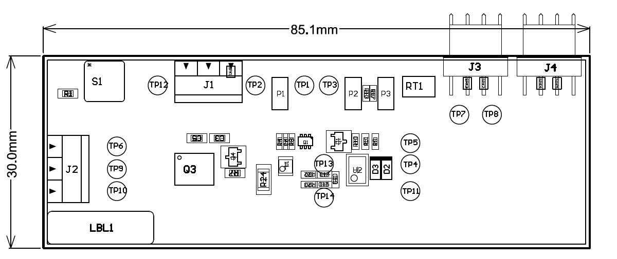
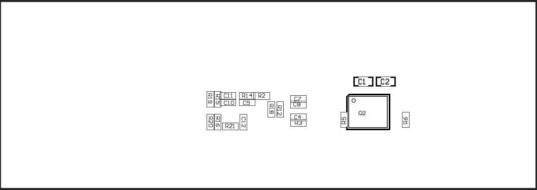
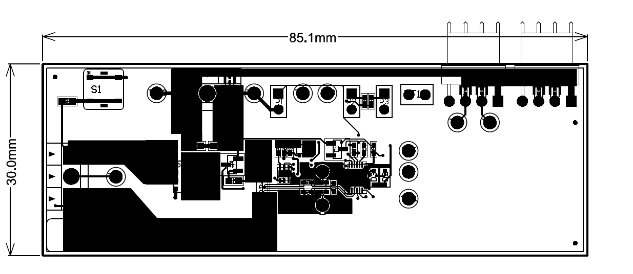
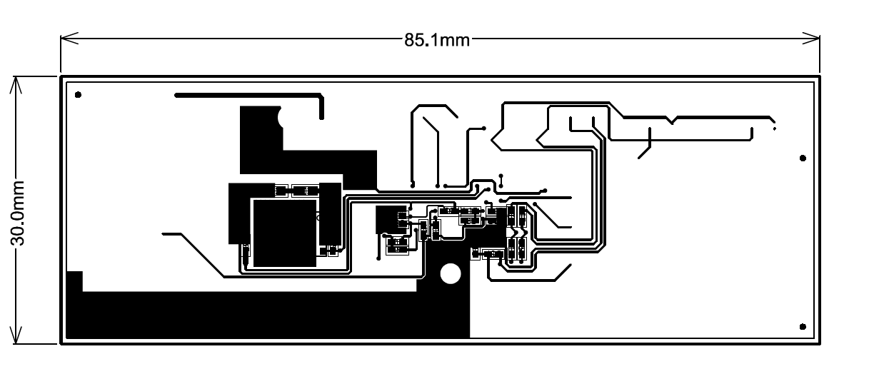
This section shows the dimensions, PCB layers (see Figure 1-13 through Figure 1-18), and assembly drawing for the BQ28Z620 modules.
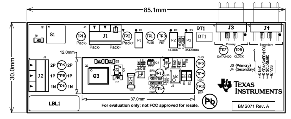
GUID-9151E117-ED45-4E25-86E3-489A81C857C1-low.png Figure 1-13 Top Silk Screen
GUID-A5FBBA99-A685-4B11-B7C9-C32CF95309F2-low.png Figure 1-14 Bottom Silk Screen
GUID-A7279A15-5A87-4BA3-9380-65E5C1616B24-low.png Figure 1-15 Top Assembly
GUID-9CE40FE6-B252-47BC-ACDB-B1E21DCC7B74-low.png Figure 1-16 Bottom Assembly
GUID-EF6764A3-E4DD-467E-8A8D-16392629CD21-low.png Figure 1-17 Top Layer
GUID-B51B17B9-B68D-41EF-B287-2918676C3FF8-low.png Figure 1-18 Bottom Layer