SLUUCV9 November   2023 TPS4800-Q1


  1.   1
  2.   Description
  3.   Features
  4.   Applications
  5.   5
  6. 1Evaluation Module Overview
    1. 1.1 Introduction
    2. 1.2 Kit Contents
    3. 1.3 Specification
    4. 1.4 Device Information
  7. 2Hardware
    1. 2.1 Setup
    2. 2.2 General Configurations
      1. 2.2.1 Physical Access
      2. 2.2.2 Test Equipment and Setup
        1. 2.2.2.1 Power Supplies
        2. 2.2.2.2 Meters
        3. 2.2.2.3 Oscilloscope
        4. 2.2.2.4 Loads
  8. 3Implementation Results
    1. 3.1 Test Setup and Procedures
      1. 3.1.1 Power-Up With EN Control
      2. 3.1.2 ON and OFF Control With INP Input
      3. 3.1.3 Overload and Short Circuit Protection Test
      4. 3.1.4 Overvoltage Protection Test
      5. 3.1.5 Short-Circuit Protection Diagnosis Test
      6. 3.1.6 Input Reverse Polarity Test
  9. 4Hardware Design Files
    1. 4.1 Schematic
    2. 4.2 PCB Layout
    3. 4.3 Bill Of Materials (BoM)
  10. 5Additional Information
    1.     Trademarks

Overvoltage Protection Test

Use the following instructions to perform the overvoltage test:

  1. Set the input supply voltage VIN to 48 V and current limit of 10 A
  2. Enable the power supply.
  3. Now, gradually increase the VIN voltage to observe the overvoltage cutoff response of TPS48000-Q1 using an oscilloscope.
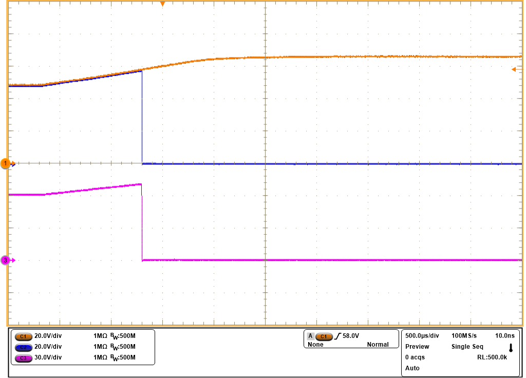
GUID-20231103-SS0I-NFLT-F6V4-7HQWW0WW0JRR-low.pngFigure 3-10 Overvoltage Cut-off Response of TPS48000-Q1 at 58-V Level