SLUUCW4 November   2023 BQ27Z558


  1.   1
  2.   Description
  3.   Features
  4.   Applications
  5.   5
  6. 1Evaluation Module Overview
    1. 1.1 Introduction
    2. 1.2 Kit Contents
    3. 1.3 Specification
    4. 1.4 Device Information
  7. 2Hardware
    1. 2.1 Hardware Setup
      1. 2.1.1 Hardware Requirements
      2. 2.1.2 Connecting the BQ27Z558 Circuit Module to a Battery Pack
      3. 2.1.3 EVM Jumpers Description
    2. 2.2 Chemical ID
      1. 2.2.1 Chemical ID Selection Process Description
      2. 2.2.2 Hardware Requirements and Setup
      3. 2.2.3 Logging Data in bqStudio
      4. 2.2.4 GPCChem Tool
      5. 2.2.5 Programming a Chemical ID
      6. 2.2.6 Further Resources for Chemical ID Process
    3. 2.3 Calibrating Gauge Measurements
      1. 2.3.1 Voltage Calibration
      2. 2.3.2 Current Calibration
    4. 2.4 Learning Cycle and Golden Image
      1. 2.4.1 Learning Cycle Process Description
      2. 2.4.2 Data Memory Configuration
      3. 2.4.3 Learning Cycle Steps
      4. 2.4.4 Low Temperature Optimization
      5. 2.4.5 Creating the Golden Image File
      6. 2.4.6 Programming the Golden Image File
    5. 2.5 BQ27Z558-Based Circuit Module
      1. 2.5.1 Circuit Module Connections
      2. 2.5.2 Pin Description
  8. 3Software
    1. 3.1 Software Setup
      1. 3.1.1 System Requirements
      2. 3.1.2 Software Installation
    2. 3.2 Troubleshooting Unexpected Dialog Boxes
    3. 3.3 Using bqStudio
      1. 3.3.1 Starting the Program
      2. 3.3.2 Setting Programmable BQ27Z558 Options
    4. 3.4 Gauge Communication
      1. 3.4.1 Advanced Communication in bqStudio
      2. 3.4.2 Standard Data Commands
      3. 3.4.3 Manufacturer Access Commands
      4. 3.4.4 Further Resources on Gauge Communication
  9. 4Hardware Design Files
    1. 4.1 Schematic
    2. 4.2 PCB Layout
    3. 4.3 Bill of Material
  10. 5Additional Information
    1.     Trademarks

Chemical ID Selection Process Description

The test consists of the following steps:

  1. Test is performed at room temperature. If the cell was at a different temperature, let the cell relax for two hours at room temperature prior to the test.
  2. Charge using CC or CV charging to full using taper current (for example, C/100). Use nominal CC charge rate and CV voltage. If another charging method is specified by the cell maker, use that method.
  3. Let the battery relax for two hours to reach full equilibrium open circuit voltage (OCV).
  4. Discharge the battery at C/10 rate until the minimal voltage (as specified by the cell manufacturer) is reached.
  5. Let the battery relax for five hours to reach full equilibrium OCV.

Figure 2-2 shows an example of what this process looks like graphically.
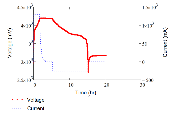
GUID-BAB93D24-CAF1-466C-A806-F625FF0B395F-low.pngFigure 2-2 Graph of IV Data in Charge-Relax-Discharge-Relax