SLUUCW5 November 2023 UCC28750
3.1.2 Startup
CH1 =VBULK , CH2 = VCC, CH3 = VGATE, CH4 = VOUT
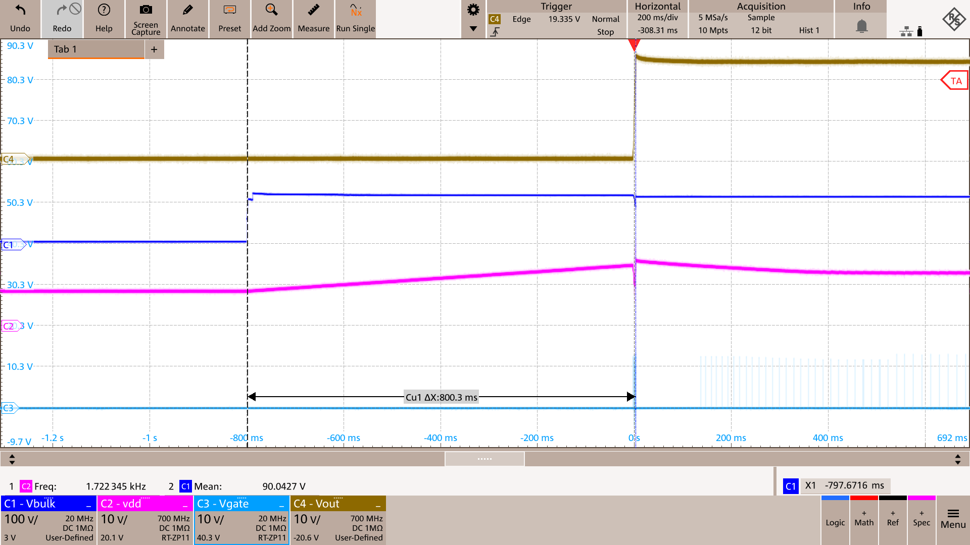 Figure 3-2 Start-up Waveforms at 85Vac and No Load
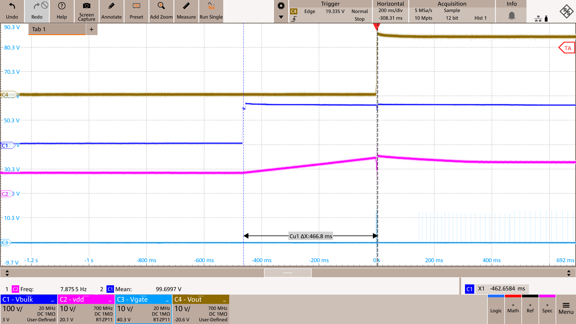 Figure 3-4 Start-up Waveforms at 115Vac and No Load
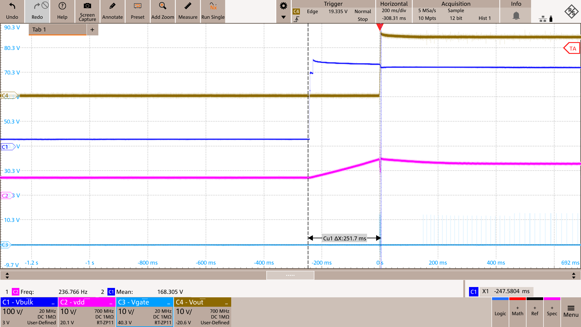 Figure 3-6 Start-up Waveforms at 230Vac and No Load
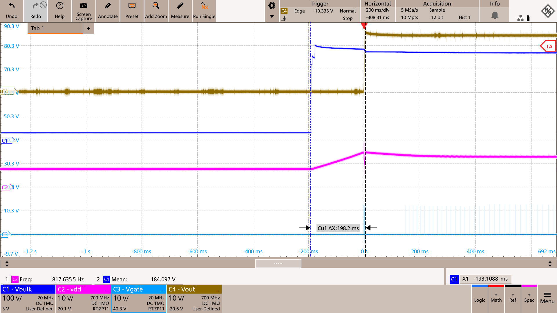 Figure 3-8 Start-up Waveforms at 265Vac and No Load
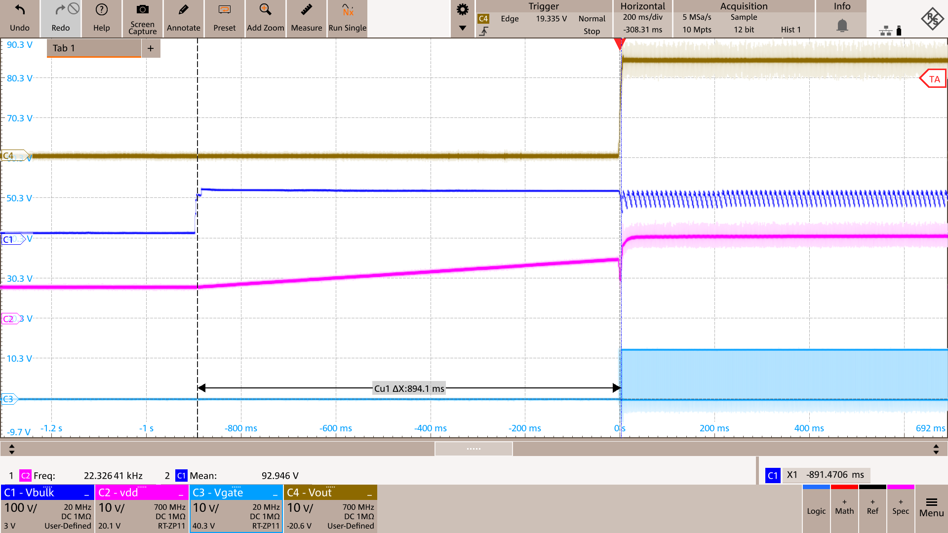 Figure 3-3 Start-up Waveforms at 85Vac and Full Load
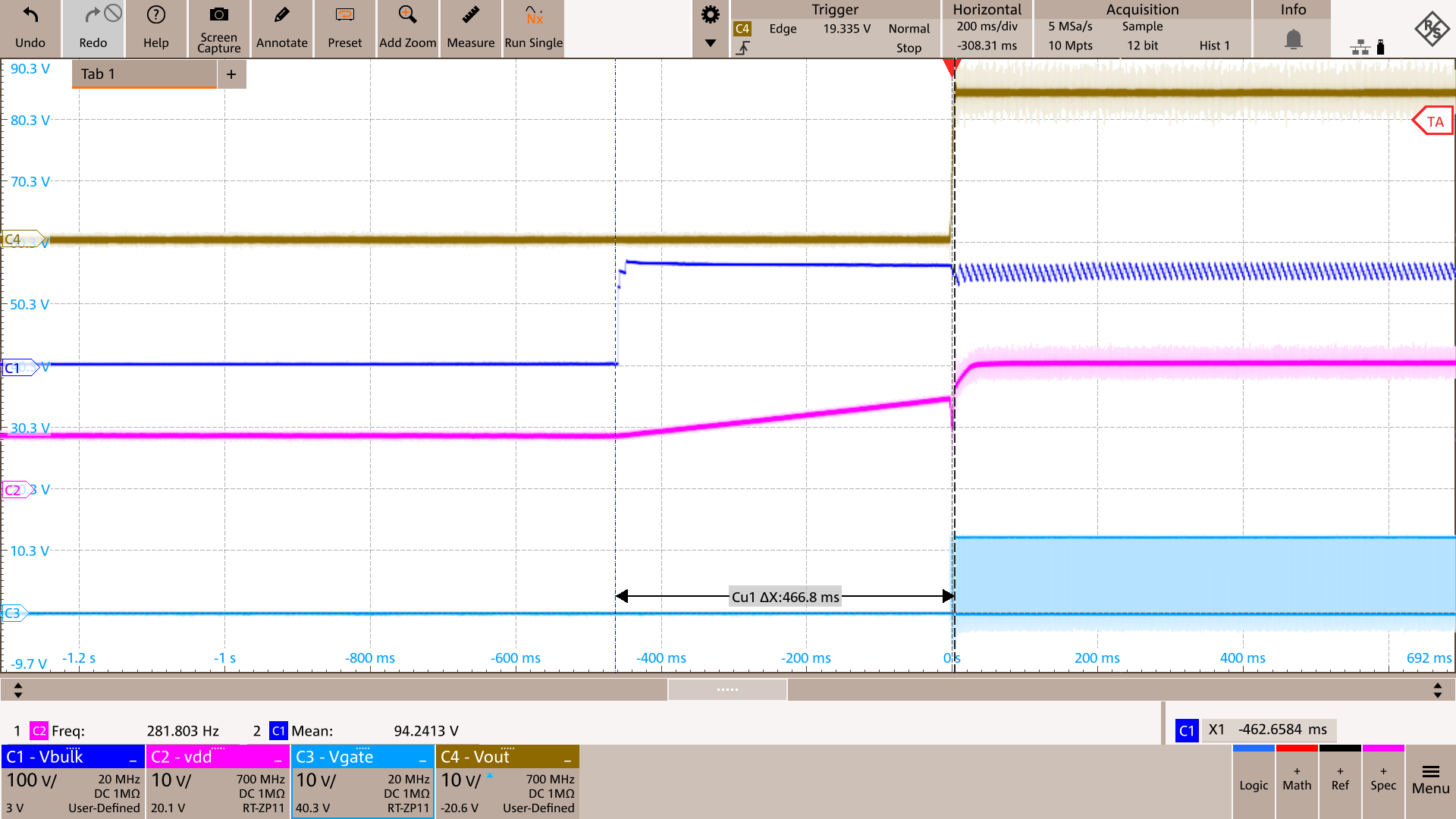 Figure 3-5 Start-up Waveforms at 115Vac and Full Load
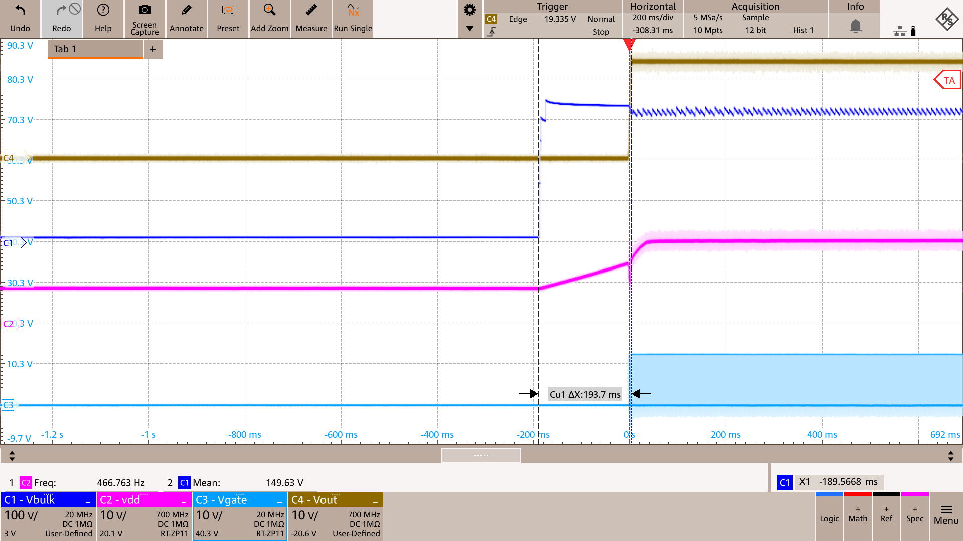 Figure 3-7 Start-up Waveforms at 230Vac and Full Load
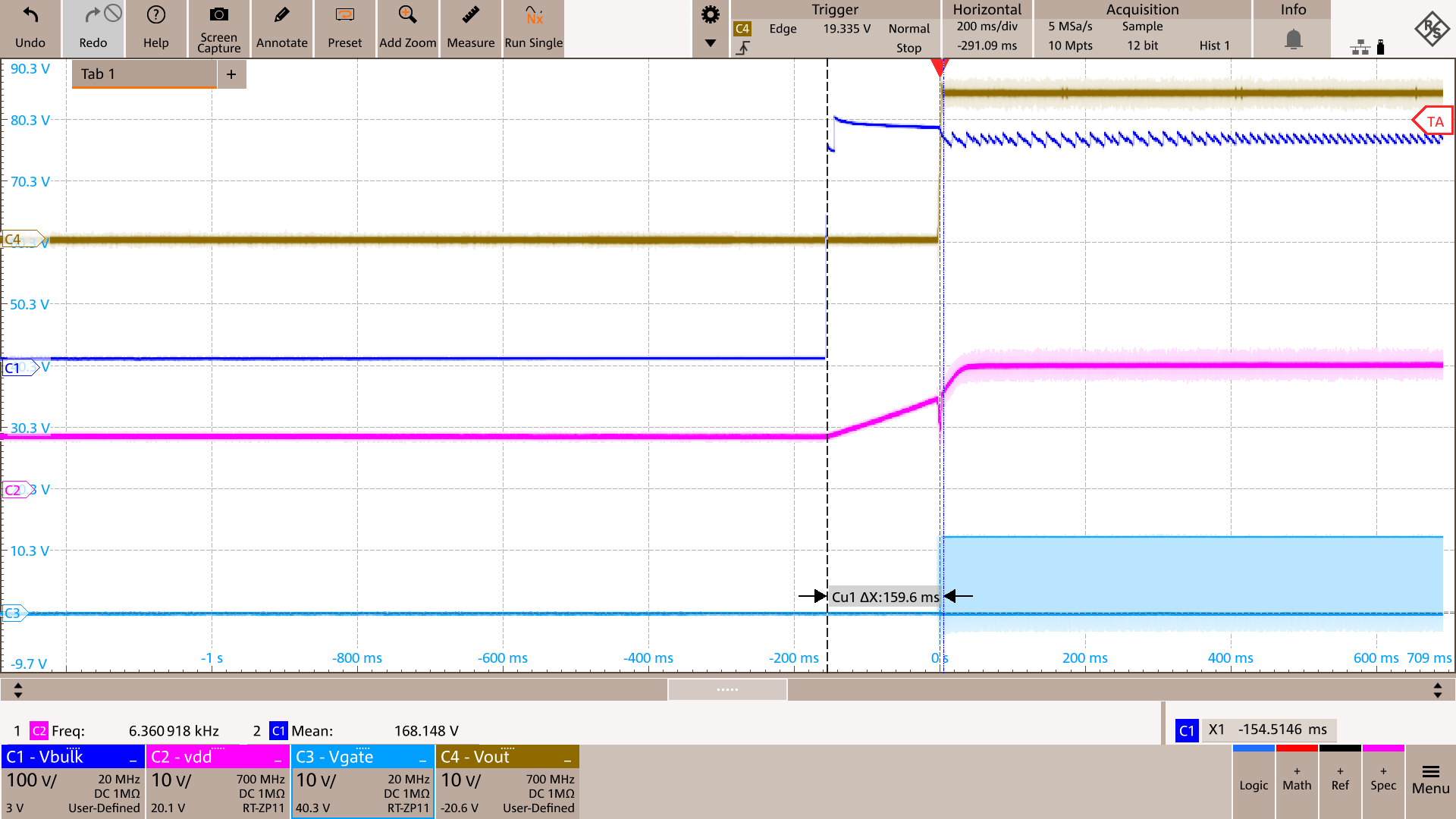 Figure 3-9 Start-up Waveforms at 265Vac and Full Load