SLUUCW7 july   2023 TPS25983


  1.   1
  2.   Description
  3.   Features
  4.   Applications
  5.   5
  6. 1Evaluation Module Overview
    1. 1.1 Introduction
    2. 1.2 Kit Contents
    3. 1.3 Specification
    4. 1.4 Device Information
  7. 2Hardware
    1. 2.1 Test Points and Connectors
    2. 2.2 Test Equipment and Set Up
      1. 2.2.1 Power Supplies
      2. 2.2.2 Meters
      3. 2.2.3 Oscilloscope
      4. 2.2.4 Loads
    3. 2.3 Test Setup and Procedures
      1. 2.3.1 Hot-Plug Test
      2. 2.3.2 Current Limit Test
      3. 2.3.3 Output Hot-Short Test
      4. 2.3.4 Wakeup into Short Test
      5. 2.3.5 Overvoltage Cut-off Test
  8. 3Hardware Design Files
    1. 3.1 Schematic
    2. 3.2 PCB Layouts
    3. 3.3 Bill Of Materials (BOM)
  9. 4Additional Information
    1.     Trademarks

PCB Layouts

Figure 4-2 shows component placement of the EVAL Board and Figure 4-3 shows PCB layout images.
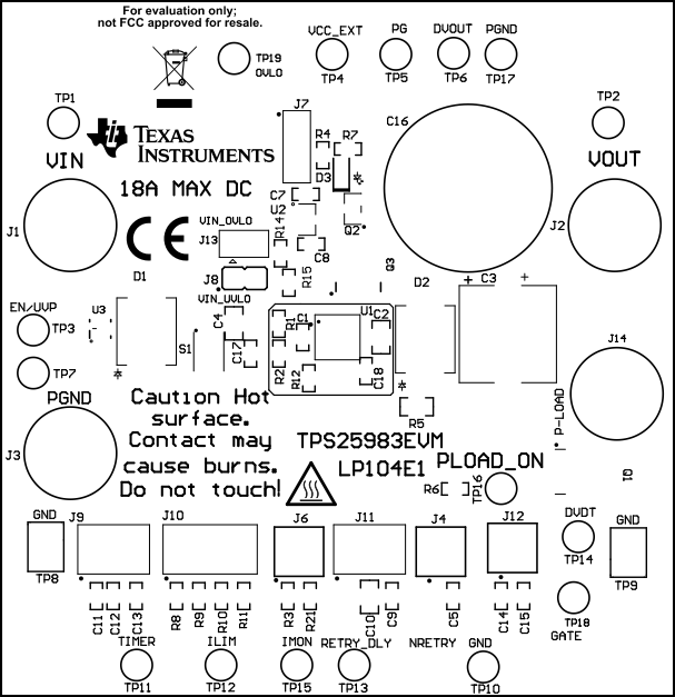
GUID-20230628-SS0I-3TRL-2BPJ-NBNTPW1LRWHL-low.gifGUID-20230628-SS0I-K1ZJ-XD5S-CCNSTNPKG3WB-low.gifFigure 3-2 TPS25983EVM Board (a) Top Assembly (b) Bottom Assembly
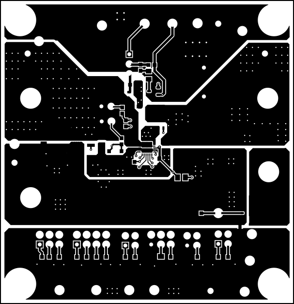
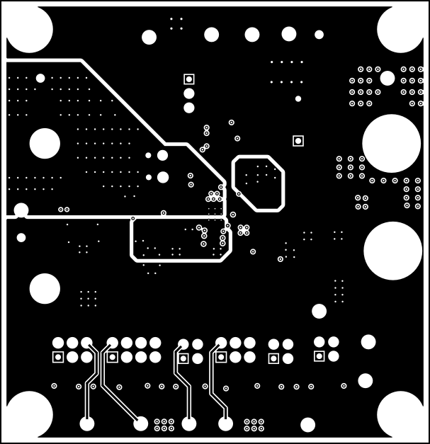
GUID-20230628-SS0I-DCWN-XXGC-PQXQKZDGK1PM-low.gifGUID-20230628-SS0I-PD7H-DZMF-N0VHNFNRTHPL-low.gifFigure 3-3 TPS25983EVM Board (a) Top Layer (b) Bottom Layer