SLUUCX0A February 2024 – June 2024 UCC57108
3.3 Bench Setup
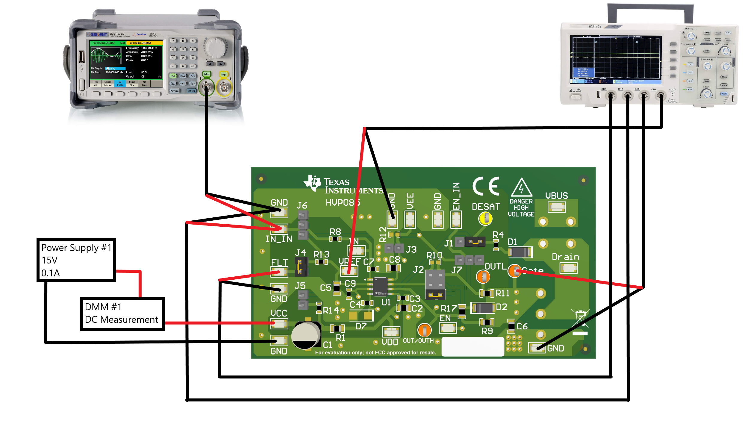
Please follow the connection procedure below and Figure 4-1 can be used as a reference.
- Make sure all the output of the function generator, and voltage source are off before connection.
- Function generator Ch-A channel applied on IN_IN.
- Power Supply:
- Power supply #1: positive node connected to input of DMM #1 and DMM #1 output connected to test point marked as VCC, negative node of Power Supply #1 connected directly to test point marked as GND.
- Oscilloscope:
- FAULT Signal: Connect oscilloscope Ch-1 probes to test points marked as FLT to GND, smaller measurement loop is preferred.
- IN Signal: Connect oscilloscope Ch-2 probes to test points marked as IN_IN to GND, smaller measurement loop is preferred.
- OUT Signal: Connect oscilloscope Ch-3 probes to test points marked as Gate to GND, smaller measurement loop is preferred.
- VREF Signal: Connect oscilloscope Ch-4 probes to test points marked as VREF to GND, smaller measurement loop is preferred.
 Figure 3-1 Bench Setup Diagram