SLUUCX7 September 2023
- 1
- Description
- Features
- Applications
- 5
- 1Evaluation Module Overview
- 2Hardware
-
3Implementation Results
- 3.1 Electrical Performance Specifications
- 3.2 Test Setup
- 3.3
Performance Data and Typical Characteristic Curves
- 3.3.1 Efficiency Result of 4-Point Average on 20-Vout
- 3.3.2 Efficiency Result of 4-Point Average at 15-Vout
- 3.3.3 Efficiency Result of 4-Point Average at 9-Vout
- 3.3.4 Efficiency Result of 4-Point Average at 5-Vout
- 3.3.5 Efficiency Typical Results
- 3.3.6 Output Characteristics
- 3.3.7 Switching Frequency
- 3.3.8 Key Switching Waveforms
- 3.3.9 Output Ripple Voltage
- 3.3.10 Load Transient Response
- 3.3.11 EN55022 Class B Conducted EMI Test Result
- 3.3.12 Thermal Images at Full Load (20 V and 3.25 A)
- 4Hardware Design Files
- 5Additional Information
3.3.12 Thermal Images at Full Load (20 V and 3.25 A)
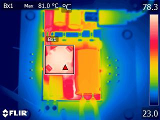 Figure 3-36 VIN = 90
VAC, Top Side
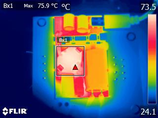 Figure 3-38 VIN = 115
VAC, Top Side
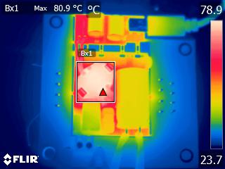 Figure 3-40 VIN = 230
VAC, Top Side
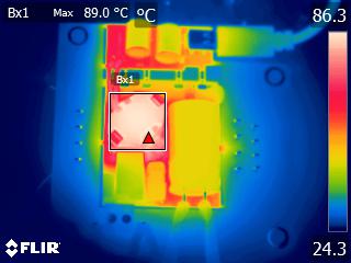 Figure 3-42 VIN = 265
VAC, Top Side
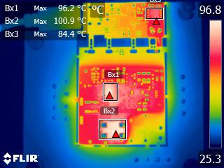 Figure 3-37 VIN = 90
VAC, Bottom Side
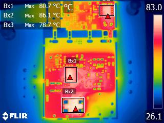 Figure 3-39 VIN = 115
VAC, Bottom Side
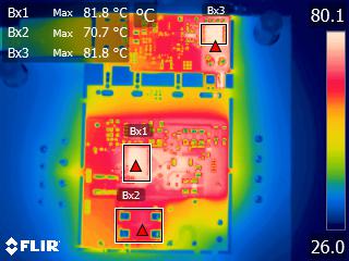 Figure 3-41 VIN = 230
VAC, Bottom Side
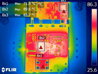 Figure 3-43 VIN = 265
VAC, Bottom Side