SLUUCZ5 December 2024 TPS54538
2.1.1 EVM Connections
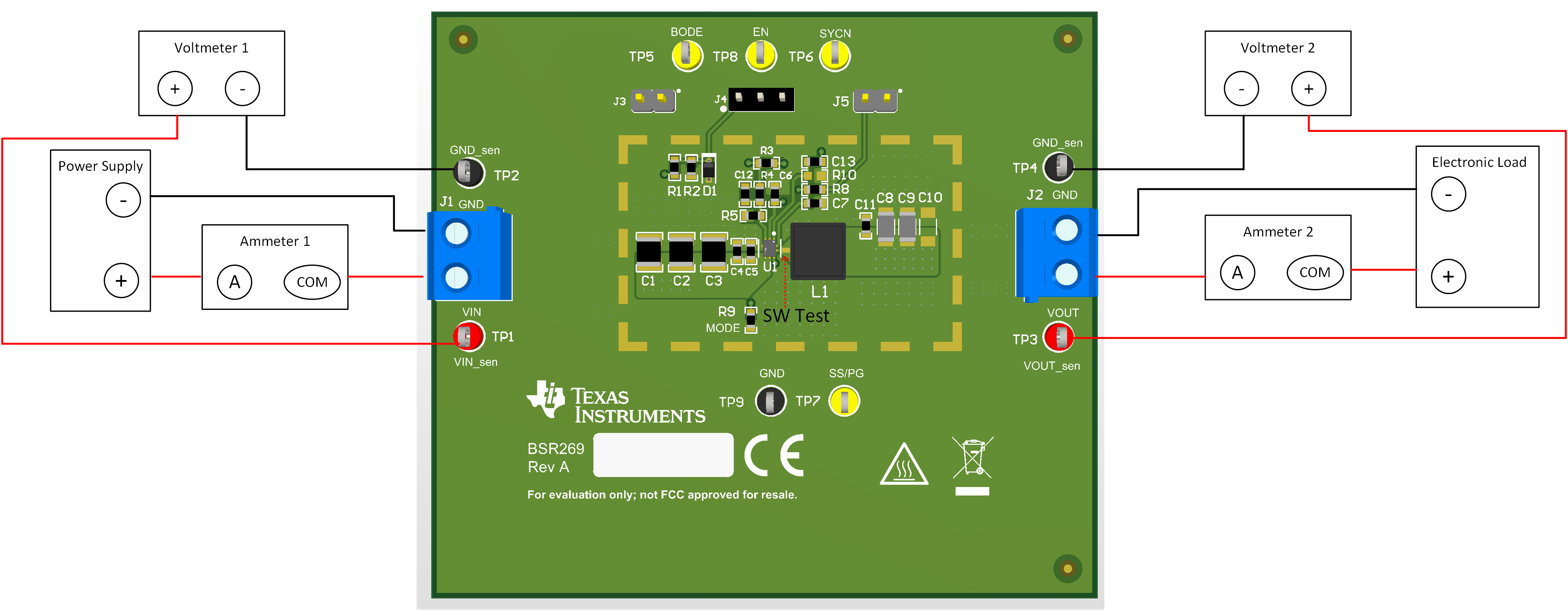
Referencing the EVM connections described in Table 2-1, the recommended test setup to evaluate the TPS54538 is shown in Figure 2-1. Working at an ESD-protected workstation, make sure that any wrist straps, boot straps, or mats are connected and referencing the user to earth ground before handling the EVM.
 Figure 2-1 EVM Test Setup
| LABEL | DESCRIPTION |
|---|---|
| VIN (J1) | Positive input voltage to the converter |
| GND (J1) | Negative input voltage to the converter |
| VOUT (J2) | Positive output voltage of the converter |
| GND (J2) | Negative output voltage of the converter |
| LABEL | DESCRIPTION |
|---|---|
VIN_sen(TP1) | Measure input voltage. |
VOUT_sen(TP3) | Measure output voltage. |
GND(TP9) | Ground of the converter. |
SS/PG (TP7) | Soft-Start function or Power-Good function depending on the mode selection. |
| BODE(TP5) | Injection point for loop response. |
EN (TP8) | EN indicator of converter. |
SYNC (TP6) | SYNC clock injection. |
Header (J3 and J4) | Leaving J3 and J4 open enables the converter. Connect (PIN-1 to PIN-2) of J3 and (PIN-1 to PIN-2) of J4 can set system UVLO voltage with an external resistor divider R1 and R2. Connect (PIN-1 to PIN-2) of J3 and (PIN-2 to PIN-3) of J4 can disable the converter. |
| Header (J5) | When Power-Good mode selected, connecting (PIN-1 to PIN-2) of J5 for PG pin connected to pullup voltage. |