SLUUD32 June   2024 BQ41Z50


  1.   1
  2.   Description
  3.   Features
  4.   4
  5. 1Evaluation Module Overview
    1. 1.1 Introduction
    2. 1.2 Kit Contents
    3. 1.3 Specification
    4. 1.4 Device Information
  6. 2BQ41Z50EVM Quick Start Guide
    1. 2.1 Items Needed for EVM Setup and Evaluation
    2. 2.2 Software Installation
    3. 2.3 EVM Connections
    4. 2.4 Update Firmware
  7. 3Hardware
    1. 3.1 BQ41Z50 Production Calibration Guide
  8. 4Software
    1. 4.1 Battery Management Studio
      1. 4.1.1 Registers Screen
      2. 4.1.2 Setting Programmable BQ41Z50 Options
      3. 4.1.3 Calibration Screen
        1. 4.1.3.1 Voltage Calibration
        2. 4.1.3.2 Temperature Calibration
        3. 4.1.3.3 Current Calibration
      4. 4.1.4 Chemistry Screen
      5. 4.1.5 Firmware Screen
        1. 4.1.5.1 Programming the Flash Memory
        2. 4.1.5.2 Exporting the Flash Memory
      6. 4.1.6 Advanced Comm SMB Screen
  9. 5Hardware Design Files
    1. 5.1 BQ41Z50EVM Circuit Module Schematic
      1. 5.1.1 LED Control
    2. 5.2 Circuit Module Physical Layouts
      1. 5.2.1 Board Layout
      2. 5.2.2 Schematic
    3. 5.3 Bill of Materials
  10. 6Additional Information
    1. 6.1 Trademarks
  11. 7Related Documentation from Texas Instruments

Setting Programmable BQ41Z50 Options

The BQ41Z50 data flash comes configured per the default settings detailed in the BQ41Z50 TRM. Make sure that the settings are correctly changed to match the pack and application for the design being evaluated.

Note:

The correct setting of these options is essential to get the best performance. The settings can be configured using the Data Memory screen (see Figure 5-2).
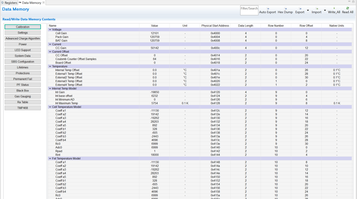
BQ41Z50EVM Data Memory Screen Figure 4-2 Data Memory Screen