SLUUD47 October 2024 BQ21088
2.3.2 Charge Mode
Connect the equipment as the following:
- Power Supply PS#1: VIN of the BQ21088 at 5V.
- Power supply PS#2: VBAT of the BQ21088 at 3.7V.
- Scope Channel SC#1: VIN
- Scope Channel SC#2: VSYS.
- Scope Channel SC#3: VBAT
Turn the supply PS#2 on, then turn the supply PS#1 on. The VSYS rises to 4.5V. The device begins to charge as long as the TS is left at default configuration and there are no other faults.
 Figure 2-1 BQ21088 EVM
Connections
Figure 2-1 BQ21088 EVM
ConnectionsTo adjust the charge current or change other parameters, connect the USB2ANY to the EVM and then start up the TI Charger GUI.
Note: If the supplies (VIN and VBAT) are turned off,
then users need to restart the TI Charger GUI for the correct I2C
transactions to be reflected in the TI Charger GUI.
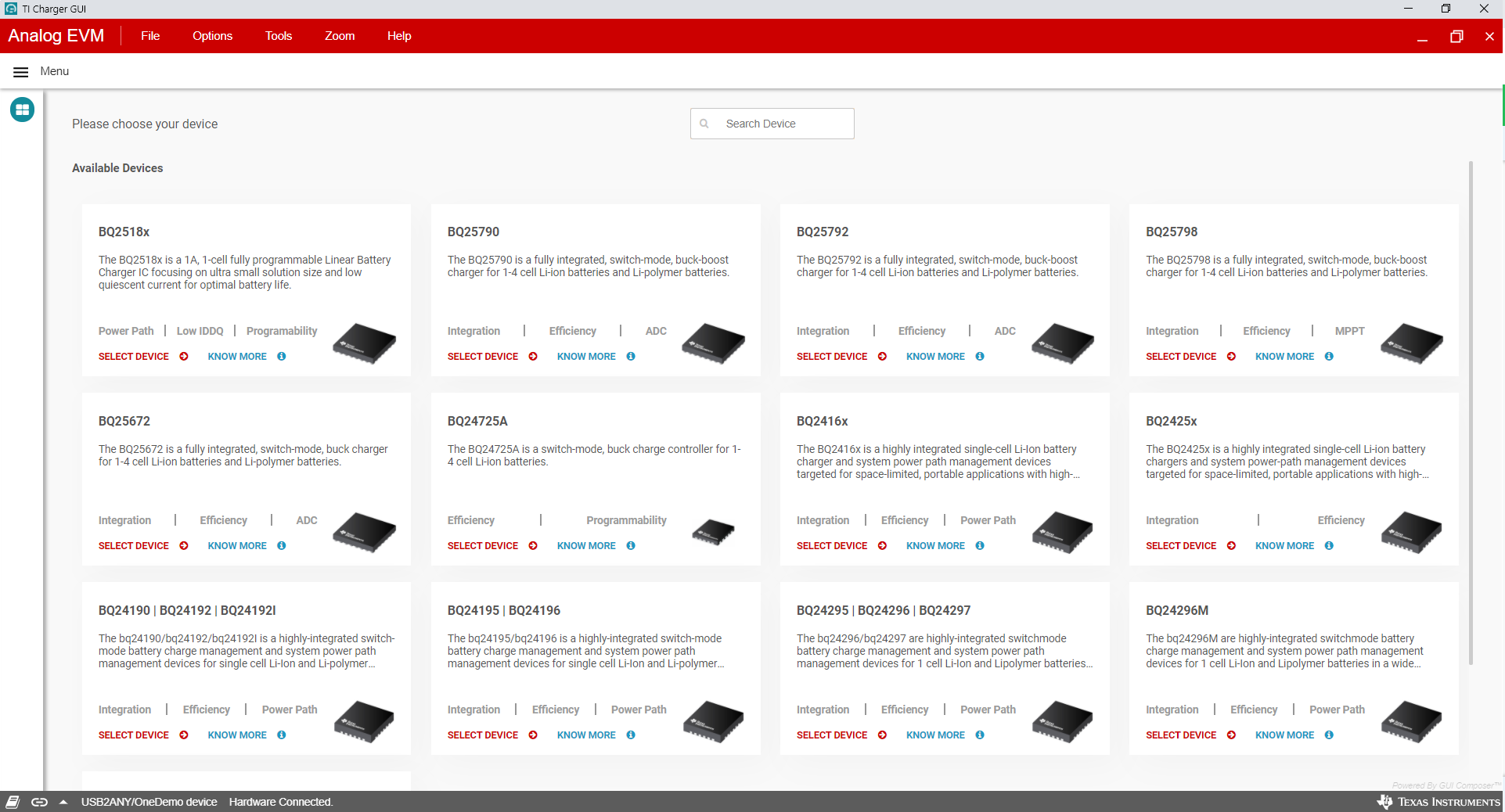
 Figure 2-2 TI Charger GUI Device Selection
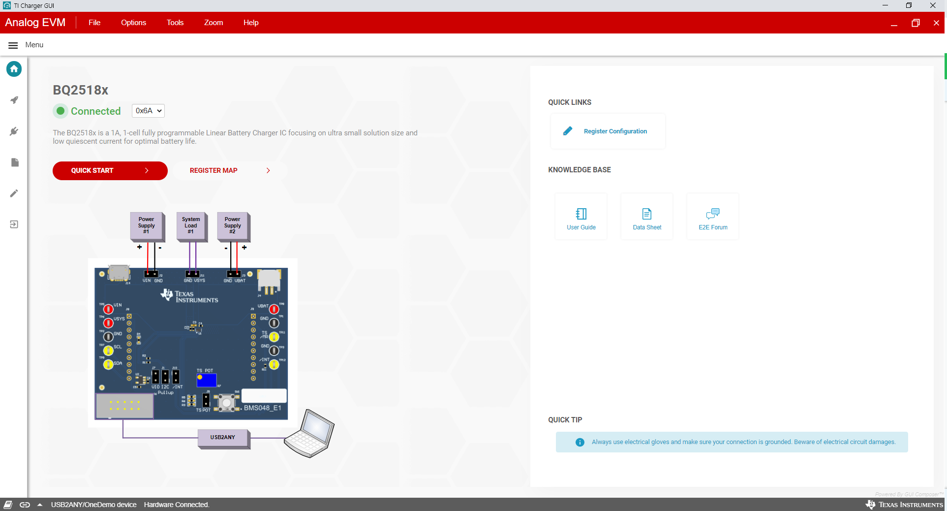
Select the BQ2518X from the charger selection. Click Quick Start or Register Map.
 Figure 2-3 BQ21088EVM Connected
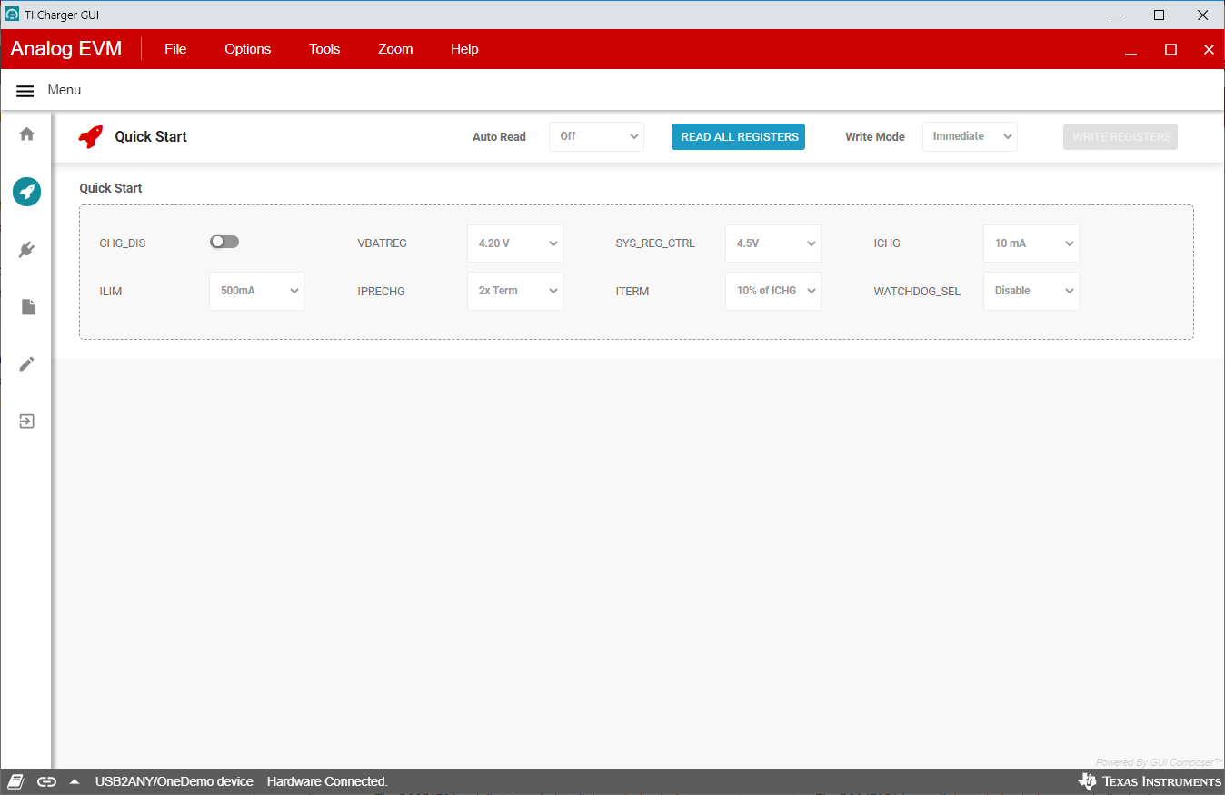
The Quick Start is shown in Figure 2-4.
 Figure 2-4 Quick Start
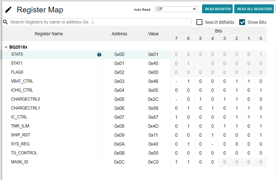
The register map is shown in Figure 2-5.
 Figure 2-5 Register Map