SLVA528D September 2012 – August 2021 TPS65381-Q1 , TPS65381A-Q1
- Trademarks
- 1Introduction
- 2Product Overview
- 3Development Process for Management of Systematic Faults
- 4TPS65381x-Q1 Product Architecture for Management of Random Faults
-
5TPS65381x-Q1 Architecture Safety Mechanisms and Assumptions of Use
- 5.1 Power Supply
- 5.2 Regulated Supplies
- 5.3
Diagnostic, Monitoring, and Protection Functions
- 5.3.1 External MCU Fault Detection and Management
- 5.3.2 Voltage Monitor (VMON)
- 5.3.3 Loss-of-Clock Monitor (LCMON)
- 5.3.4 Junction Temperature Monitoring and Current Limiting
- 5.3.5 Analog and Digital MUX (AMUX and DMUX) and Diagnostic Output Pin (DIAG_OUT)
- 5.3.6 Analog Built-In Self-Test (ABIST)
- 5.3.7 Logic Built-In Self-Test (LBIST)
- 5.3.8 Device Configuration Register Protection
- 6Application Diagrams
- 7TPS65381x-Q1 as Safety Element out of Context (SEooC)
- 8Revision History
5.3.1.2 Watchdog Timer
The watchdog timer monitors proper function of the external MCU. The watchdog has two modes of operation: trigger mode or question and answer (Q&A) mode.
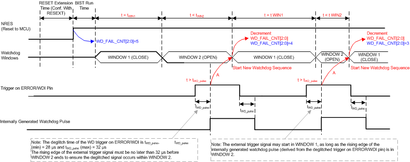
- Trigger modeThe MCU indicates normal operation by periodically sending a watchdog trigger (pulse) on the ERROR/WDI pin, which a window watchdog must receive within a defined time windows.
- Q&A modeThe MCU sends the watchdog information through SPI. The MCU reads or calculates the next question and provides four answer bytes for each question. The fourth answer byte must be in the Window 2 and all answer bytes must be correct and provided in the correct order.
The watchdog configuration is controlled by the WD_CFG bit the SAFETY_FUNC_CFG register. The default configuration is trigger mode.
Actions are taken based on a watchdog failure counter, WD_FAIL_CNT[2:0]. Good events in both modes decrement the WD_FAIL_CNT[2:0] counter and bad events increment the counter. When the WD_FAIL_CNT[2:0] counter is less than five, the ENDRV pin can be asserted high by setting the ENABLE_DRV bit. If the MCU responds incorrectly or not at all, bad events, or time-out, are detected and the WD_FAIL_CNT[2:0] counter increment. When the WD_FAIL_CNT[2:0] counter is five or greater, the ENDRV pin is not able to be asserted high, even if the ENABLE_DRV bit is set high. If the MCU does not recover and the WD_FAIL_CNT[2:0] counter reaches 7 + 1 (the next bad or time-out event after the fail counter reaches 7) while the WD_RST_EN bit is 1 the device transitions to the RESET state and the NRES pin is pulled low. If the NRES pin is connected to the reset input circuits of the MCU, the MCU is also reset.

