SLVA528D September 2012 – August 2021 TPS65381-Q1 , TPS65381A-Q1
- Trademarks
- 1Introduction
- 2Product Overview
- 3Development Process for Management of Systematic Faults
- 4TPS65381x-Q1 Product Architecture for Management of Random Faults
-
5TPS65381x-Q1 Architecture Safety Mechanisms and Assumptions of Use
- 5.1 Power Supply
- 5.2 Regulated Supplies
- 5.3
Diagnostic, Monitoring, and Protection Functions
- 5.3.1 External MCU Fault Detection and Management
- 5.3.2 Voltage Monitor (VMON)
- 5.3.3 Loss-of-Clock Monitor (LCMON)
- 5.3.4 Junction Temperature Monitoring and Current Limiting
- 5.3.5 Analog and Digital MUX (AMUX and DMUX) and Diagnostic Output Pin (DIAG_OUT)
- 5.3.6 Analog Built-In Self-Test (ABIST)
- 5.3.7 Logic Built-In Self-Test (LBIST)
- 5.3.8 Device Configuration Register Protection
- 6Application Diagrams
- 7TPS65381x-Q1 as Safety Element out of Context (SEooC)
- 8Revision History
2 Product Overview
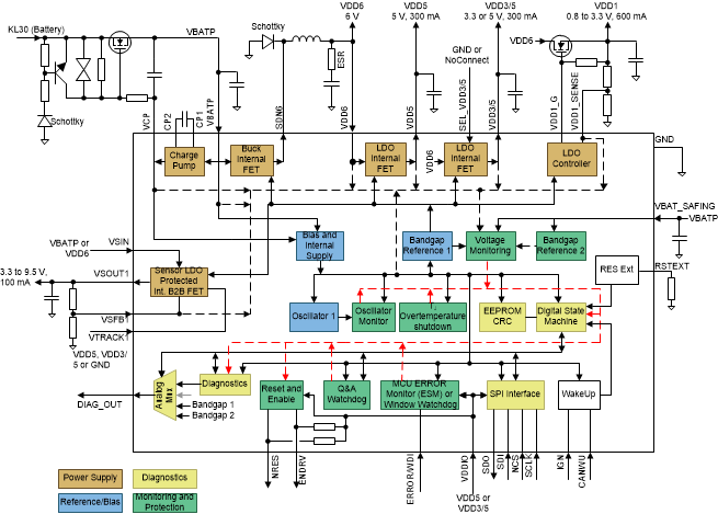
The TPS65381x-Q1 device is a multirail power supply designed to supply microcontrollers (MCUs) in safety-relevant applications, such as those found in automotive and industrial markets. The device supports Texas Instruments’ Hercules™ TMS570 MCU and C2000™ families, and various other MCUs with dual-core lockstep (LS) or loosely-coupled architectures (LC).
The TPS65381x-Q1 integrates multiple supply rails to power the MCU, transceiver (CAN or other), and an external sensor. An asynchronous buck switch-mode power-supply converter with internal FET converts the input supply (battery) to a 6-V preregulator output. This 6 V supplies the other regulators.
The integrated 5-V linear regulator with internal FET is typically used to supply a transceiver or other peripheral. A second integrated linear regulator, also with internal FET, regulates to a selectable 5-V or 3.3-V MCU I/O voltage.
The TPS65381x-Q1 includes the VDD1 voltage-regulator controller, typically used to supply the MCU core rail. This linear regulator controller uses an external FET and resistor divider (for adjustment). It regulates the 6 V to an adjustable voltage of between 0.8 V and 3.3 V for the core.
The device includes a sensor supply, VSOUT1.
The device has an integrated charge pump to provide an overdrive voltage for the internal regulators. One option for reverse-battery protection uses the charge-pump output to control an external NMOS transistor. This solution allows for a lower minimum battery voltage operation compared to a traditional reverse-battery blocking diode because there is less voltage drop across the transistor.
The device monitors undervoltage and overvoltage on all regulator outputs, battery voltage, and internal supply rails. A second band-gap reference, independent from the main band-gap reference, monitors for undervoltage and overvoltage, to avoid any drifts in the main band-gap reference being undetected. In addition, the device implements regulator current limits and temperature protections.
The TPS65381x-Q1 functional safety architecture features a watchdog configurable for question and answer (Q&A) mode or trigger mode, MCU error-signal monitor (ESM), diagnostic check for the MCU ESM, clock monitoring on internal oscillators, self-check on clock monitor, CRC on internal nonvolatile memory (EEPROM), CRC for configuration registers, diagnostic multiplex output to route internal analog (AMUX) and digital (DMUX) signals out through the DIAG_OUT pin, and a reset circuit for the MCU. A built-in self-test (BIST) allows for monitoring the device functionality at power up.
 Figure 2-1 TPS65381x-Q1 Architecture Overview