SLVAES1A June 2020 – May 2022 DRV8300
- Trademarks
- 1Motor Considerations and Why Brushless DC Motors?
- 2Motor Driver Architecture
- 3Texas Instruments' Brushless-DC Motor Drivers
- 4Conclusion
- 5Revision History
2.4.2 Sensorless
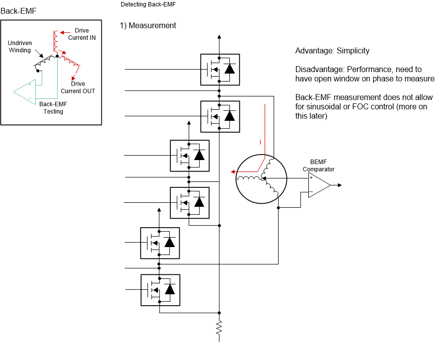
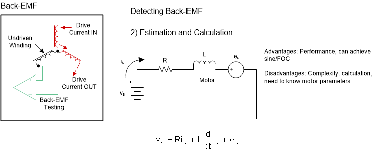
Sensorless solutions remove any sensored components from the design, which helps save on BOM costs. Many TI motor drivers can detect the position of the brushless-DC motor without the use of Hall-effect sensors by either measuring back-EMF voltages generated on unconnected windings of the motor driver (Figure 2-7) or internally estimating the back-EMF voltage (Es) generated (Figure 2-8) using winding resistance (R), winding inductance (L), phase current (Is), and motor voltage (Vs).
Sensorless control is typically used for speed applications since the motor generates enough Back-EMF when it is spinning at a constant speed. Position control cannot be sensorless, and torque control is difficult to implement sensorlessly.
 Figure 2-7 Estimating Back-EMF Using a
BEMF Comparator
 Figure 2-8 Calculating Back-EMF Using
Known Motor Parameters and a First-Order Differential Equation