-
How to Extend Operating Time of a LiSOCl2 Powered System
How to Extend Operating Time of a LiSOCl2 Powered System
Tech Note
The non-rechargeable lithium thionyl chloride (LiSOCl2) batteries are widely used in low current long-term applications like smart gas and water meters, asset tracking (for trucks, container, animals), building and factory automation (like alarms, motion detectors and fault indicators) and many other applications. The high capacity, high energy density and low self-discharge rate makes these batteries the ideal candidate for those long-term applications. However, the batteries have a limited output current capability and depending on the discharge rate the capacity varies significantly.
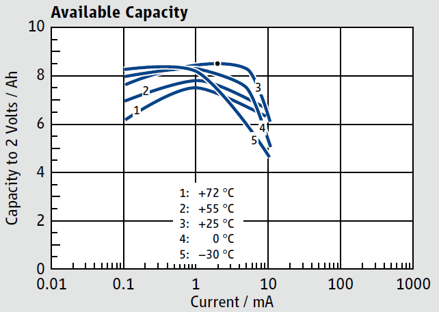 Figure 1-1 Tadiran SL-2870 Capacity
 As an example, look at the Tadiran SL-2870 C-Cell with rated 8.5 Ah nominal capacity. Figure 1-1 shows the capacity vs output current at different temperatures. The maximum capacity is available at 2-mA load current at 25°C. If the average load current is 10 mA the capacity drops to 6 Ah. That is a 30% reduction. This is caused by the increase of the internal resistance. At very low discharge currents the capacity drops again, as the self-discharge becomes more dominant. Furthermore, if temperature dependency is considered the ideal continuous discharge is around 2.5 mA. This ensures minimum capacity losses due to temperature.
A typical application that uses this battery is a IoT sensor node, that transmits the sensor data only a few times a day with a NB-IoT module. The standard use case is to add a big and expensive HLC in parallel with the battery and supply the system direct. This has the drawback that the HLC charging current is not controlled.
The TPS63900, a highly-efficient synchronous buck-boost converter with typical ultra-low quiescent current of 75 nA, solves this drawback by introducing a programmable input current limit (ICL). The typical ICL values are 1 mA, 2.5 mA, 5 mA, 10 mA, 25 mA, 50 mA and 100 mA. The lower current settings can be used to maximize the capacity of the LiSOCl2 battery. The efficiency of greater than 90% for 10 -μA load currents is not impacted, when ICL is used.
Figure 1-2 shows the typical implementation of the system using the TPS63900. TPS63900 is used to limit the current drawn from the LiSOCl2 battery. This maximizes the battery capacity as previously described. With the limited current a storage element (for example, 2s EDLC supercapacitor or an HLC) is charged. This element in turn provides the current needed for the data transmission.
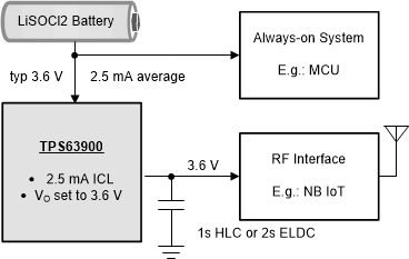 Figure 1-2 Typical Implementation Example
for Increasing LiSOCl2 Battery Capacity
Figure 1-2 Typical Implementation Example
for Increasing LiSOCl2 Battery CapacityIn addition, as described in this application note, dynamic voltage scaling (DVS) can extend the battery lifetime. It helps to save energy by lowering the supply voltage of the always on system part during low power periods. Figure 1-3 shows a modification of Figure 1-2 that combines the advantages of the ICL function and DVS of TPS63900.
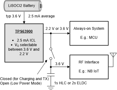 Figure 1-3 Advanced Implementation
Example for Increasing LiSOCl2 Battery Capacity Using DVS
Figure 1-3 Advanced Implementation
Example for Increasing LiSOCl2 Battery Capacity Using DVSWhen the ICL is active, the converter measures in each switching cycle how much current is transferred from the input to the output. With this information and the knowledge of VI and VO, the converter regulates the pause length between two switching cycles to keep the average input current at the set target. The inductor peak current is limited to typical 300 mA. The electric charge needed per switching cycle is provided from the input capacitor. With a typical switching cycle period of 1 μs and 300 mA peak current, only 0.3 μAs charge needs to be supplied. The input current pulses are filtered by the input capacitance and the battery internal impedance. The typical LiSOCL2 battery impedance is 1 Ω. Figure 1-4 shows the efficiency with ICL activated for VI = VO = 3.3 V.
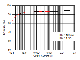 Figure 1-4 TPS63900 Efficiency With ICL
Active
Figure 1-4 TPS63900 Efficiency With ICL
ActiveThe following figures are measured at a nominal supply voltage of 3.6 V. A series resistance of 1 Ω is inserted to mimic the LiSOCL2 battery impedance. The input capacitance is increased to 100 μF to filter the switching peaks. The output voltage is set to VO = 3.3 V and CO = 330 μF. Figure 1-5 shows the start-up of the converter with 2.5 mA ICL. Figure 1-6 shows the behavior when a 100-mA load step is applied.
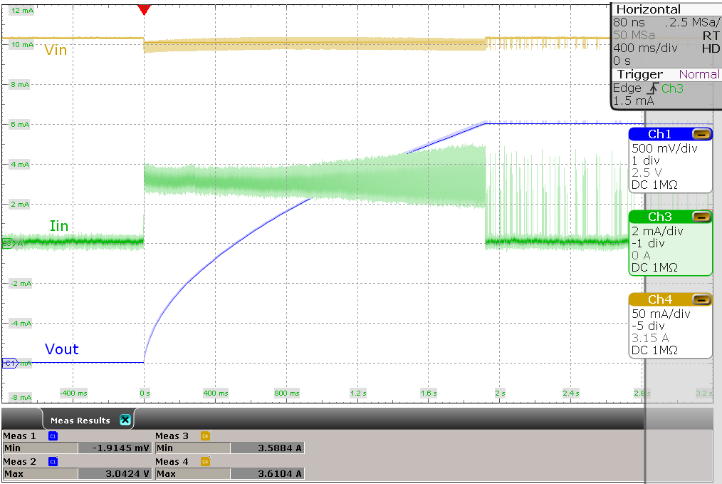 Figure 1-5 2.5-mA ICL at
Start-up
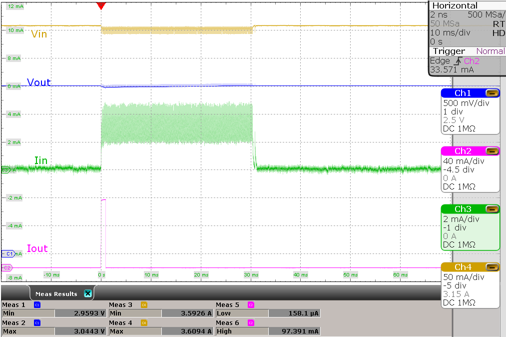 Figure 1-6 2.5-mA ICL
With 100-mA Load Step
Figure 1-6 2.5-mA ICL
With 100-mA Load StepIMPORTANT NOTICE AND DISCLAIMER
| TI PROVIDES TECHNICAL AND RELIABILITY DATA (INCLUDING DATASHEETS), DESIGN RESOURCES (INCLUDING REFERENCE DESIGNS), APPLICATION OR OTHER DESIGN ADVICE, WEB TOOLS, SAFETY INFORMATION, AND OTHER RESOURCES “AS IS” AND WITH ALL FAULTS, AND DISCLAIMS ALL WARRANTIES, EXPRESS AND IMPLIED, INCLUDING WITHOUT LIMITATION ANY IMPLIED WARRANTIES OF MERCHANTABILITY, FITNESS FOR A PARTICULAR PURPOSE OR NON-INFRINGEMENT OF THIRD PARTY INTELLECTUAL PROPERTY RIGHTS. |
| These resources are intended for skilled developers designing with TI products. You are solely responsible for (1) selecting the appropriate TI products for your application, (2) designing, validating and testing your application, and (3) ensuring your application meets applicable standards, and any other safety, security, or other requirements. These resources are subject to change without notice. TI grants you permission to use these resources only for development of an application that uses the TI products described in the resource. Other reproduction and display of these resources is prohibited. No license is granted to any other TI intellectual property right or to any third party intellectual property right. TI disclaims responsibility for, and you will fully indemnify TI and its representatives against, any claims, damages, costs, losses, and liabilities arising out of your use of these resources. |
| TI’s products are provided subject to TI’s Terms of Sale (www.ti.com/legal/termsofsale.html) or other applicable terms available either on ti.com or provided in conjunction with such TI products. TI’s provision of these resources does not expand or otherwise alter TI’s applicable warranties or warranty disclaimers for TI products. |
| Mailing Address: Texas Instruments, Post Office Box 655303, Dallas, Texas 75265
Copyright © 2020, Texas Instruments Incorporated |