SLVAEW6 December 2020 TPS2661
- Trademarks
- 1Introduction
- 2Protection Required for Current Inputs in Analog Input Modules
- 3Typical Discrete Circuit for Protection of Current Input
-
4TPS26610 for Analog Current Loop
Protection
- 4.1 Current Input Protection with TPS26610
- 4.2 Accurate Current Limiting with TPS26610
- 4.3 Leakage Current of TPS26610 and Current Measurement Accuracy
- 4.4 Protection from Mis-wiring to Field Power Supplies
- 4.5 Heating and Temperature Rise with TPS26610
- 4.6 Reduction in PCB Size with TPS26610 for Current Input Protection
- 5Conclusion
3.1.1 Over-Current Protection with Discrete Circuit
During miswiring to field power source, a current continuously flows through the burden resistor. PTCs allow a continuous current up-to IHOLD without tripping. As the current increases above ITRIP and PTCs temperature go above switch temperature or Curie point, PTCs increase resistance and add drop to loop in normal operation. ITRIP and IHOLD vary significantly (~50%) with the ambient temperature. Figure 3-2 provides the variation of ITRIP and IHOLD with temperature of a typical PTC with IHOLD = 55mA at 25°C.
 Figure 3-2 Hold and Trip Current of
PTC
Figure 3-2 Hold and Trip Current of
PTCTo operate with current inputs up-to 24mA, The PTC needs to be selected such that IHOLD is more than 24mA over operating temperature range. With PTC having IHOLD more than 24mA across operating range, ITRIP is typically more than 100mA at 25°C.
PTCs have an operating time in order of few seconds to bring down the current to the residual leakage current. Figure 3-3 provides the typical operating time of a PTC with IHOLD = 55mA.
 Figure 3-3 Operating Time of PTC
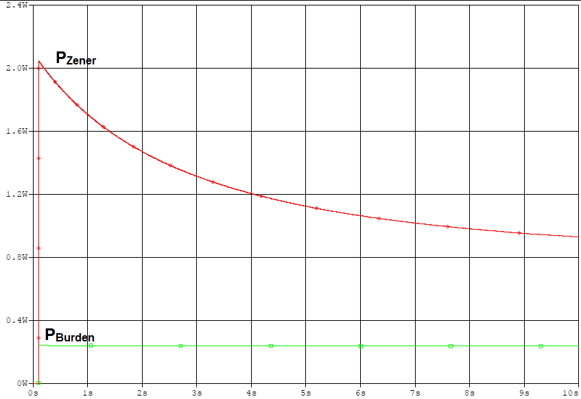
With an operating time of few seconds, a significant amount is power dissipated in burden resistor and Zener Diode. Figure 3-4 provides the power dissipated in Burden resistor and Zener Diode during miswiring to Field Supply.
 Figure 3-4 Power Dissipation in Zener and
Burden Resistor During Miswiring Faults
Figure 3-4 Power Dissipation in Zener and
Burden Resistor During Miswiring FaultsDue to the increased power dissipation in Zener and Burden resistor, the power rating of Zener has to be increased more than 2W and power rating of burden resistor has to be increased more than 300 mW for a 50-Ω burden resistor.
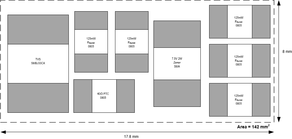
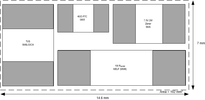
With increased power rating of Zener Diodes and Burden resistor, a Zener diode with larger package has to be used and multiple resistors in parallel are required for RBurden to dissipate the power during miswiring event.
Figure 3-5 shows a typical PCB layout with an estimated area of 142 mm2 for current input circuit with PTC, Zener and multiple 0805 (125 mW) burden resistors. Figure 3-6 shows a typical PCB layout with an estimated area of 102 mm2 for current input circuit with PTC, Zener and a 1W MELF resistor.
 Figure 3-5 PCB Size with Multiple Burden
Resistors
 Figure 3-6 PCB Size with MELF
Resistor