SLVAF40 July 2021 TPS2661
3.2 Burden Resistor and Power Dissipation
The 30-mA current limit granted by the TPS26610 allows the choice of a burden resistor with less constraints on maximum power dissipation. In overcurrent conditions the TPS26610 limits the current faster than the PTC in the typical solution.
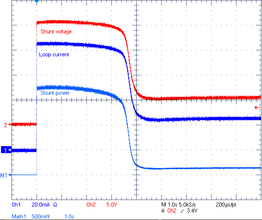
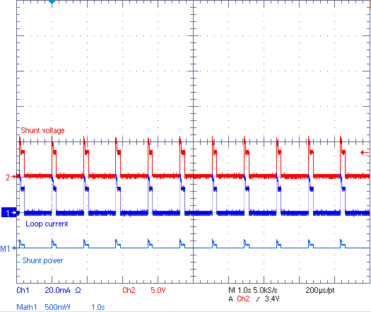
Figure 3-2 shows that in the traditional solution the burden resistor has to dissipate more than 1.7 W in about four seconds until the PTC stabilizes to around 120 mW. Figure 3-3 shows the auto-retry feature of the TPS26610 decreasing the power dissipation on the burden resistor (less than 10 mW).

Figure 3-2 PTC Overcurrent Response With VIN = 24 V (1 s/div) — 250-Ω Burden Resistor

Figure 3-3 TPS26610 Overcurrent Response With VIN = 24 V (1 s/div) — 250-Ω Burden Resistor
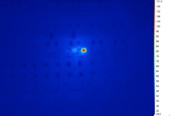
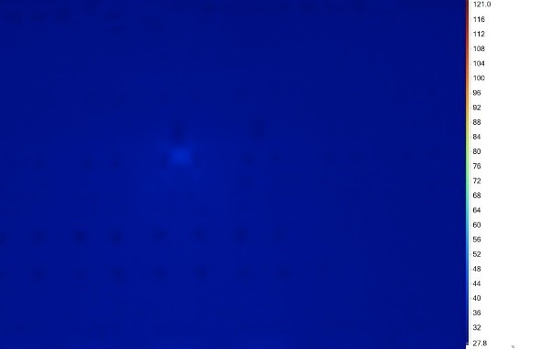
Figure 3-5 and Figure 3-4 show the temperature of the two components during the same overcurrent condition. The temperature of the TPS26610 - Figure 3-5 is 37°C while the temperature of the PTC - Figure 3-4 is more than three times higher, specifically 120°C.

Figure 3-4 PTC Thermal Image

Figure 3-5 TPS26610 Thermal Image