SLVAFC0 February 2022 TPS272C45
5 Inductive Load Test
Inductive loads such as relays and solenoids are commonly used in industrial applications How to Drive Resistive, Inductive, Capacitive, and Lighting Loads application note. The ability of TPS272C45C to drive an inductive load with repetitive switching is tested in this section. During the turn-off phase of the inductive load, the energy stored in the load will need to be dissipated, and the device needs to survive both the negative voltage at the output as well as the high thermal dissipation due to the repetitive switching.
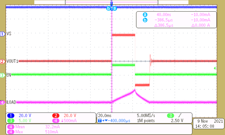
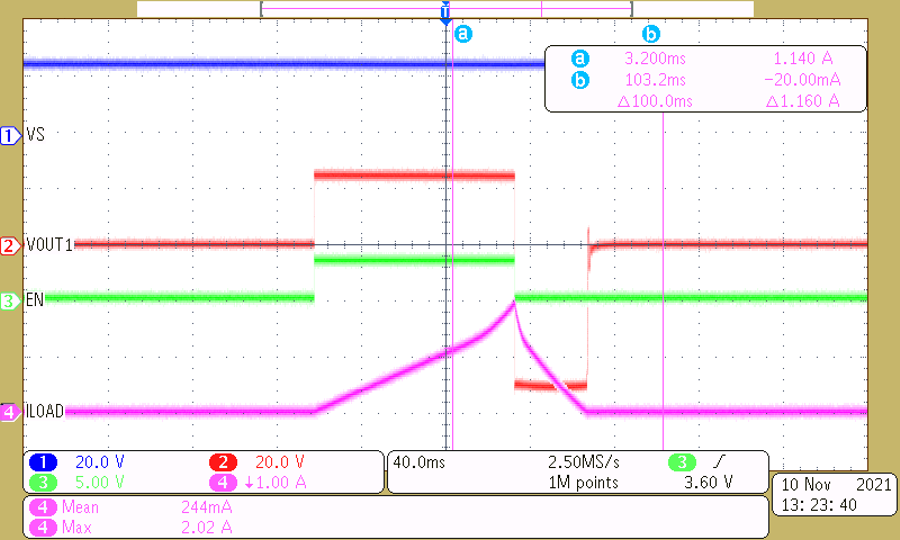
For the test setup, 24 V is applied at the input with a 1H inductor used as the load. The duty cycle for the input signal is adjusted so the turn-off current is at 500 mA and 2 A. The switching transition for the inductive load is repeated at 1 Hz for 6000 cycles.
The waveform for the switching transition at 500 mA turn-off current is shown in Figure 5-1. The output voltage at the turn-off is clamped by the VS to VOUT TVS diode, which ensures the voltage across the device is under the maximum rating. With the negative voltage at the output, the inductor is discharged quickly, and the output stabilizes to zero afterward. The device operates normally after 6000 cycles of switching.
 Figure 5-1 Waveform for the Inductive Switching Transition at 500 mA Turn-off Current
Figure 5-2 shows the turn-off current at 2 A with a longer duty cycle. The behavior is similar to the 500 mA case, and the device is operating without issues after 6000 cycles.
 Figure 5-2 Waveform for the Inductive Switching Transition at 2 A Turn-off Current