SLVAFC4 March 2022 TPS61099
1 Application Brief
Introduction
Boost converters are widely used for different markets, to provide higher output voltage from input supply like alkaline and Li-ion batteries. Most of boost converter do not directly specify maximum output current in data sheet. Engineers who misunderstand current capability specification from data sheet title can choose an improper small current converter for their system which actually demands heavier load. This application brief illustrates three steps to quickly know what is your boost converter’s output current capability.
Additionally, this application provides two examples based on TPS61022 and TPS61099. The operating condition is given as the following:
- Input voltage VIN: 1.8 V to 3.7 V;
- Output voltage VOUT: 5 V;
- Operating temperature: 25ºC;
- Target output current for TPS61022: 2 A;
- Target output current for TPS61099: 100 mA.
Step 1: Know Your Device's Input Current Limit
The current specification in data sheet title represents device’s typical input current limit. To make calculation, we need minimum value of input current limit. Minimum value is the worst current limit spec across variations. The higher this value is, the stronger current capability the device has.
For TPS61022, it has minimum valley current limit of 6.5 A as shown in Table 1-1.
| PARAMETER | TEST CONDITIONS | MIN | TYP | MAX | UNIT | |
|---|---|---|---|---|---|---|
| ILIM,SW | Valley current limit | VIN = 3.6 V, VOUT = 5 V, | 6.5 | 8 | 10 | A |
For TPS61099, as shown in Table 1-2, it has minimum current limit of 0.8 A for VOUT≥2.5 V.
| PARAMETER | TEST CONDITIONS | MIN | TYP | MAX | UNIT | |
|---|---|---|---|---|---|---|
| ILIM | Current limit threshold | VOUT ≥ 2.5 V, boost operation | 0.8 | 1 | 1.25 | A |
| VOUT < 2.5 V, boost operation | 0.5 | 0.75 | A | |||
Step 2: Know Your Device’s Efficiency Level at Interested Operating Condition
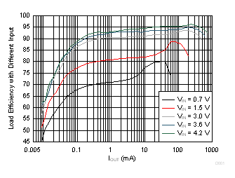
Efficiency data is needed to build relation between input current limit and output current. We need efficiency in the worst case to make sure device not enter current limit across operating conditions. The worst case for boost converter is at minimum input voltage, highest VOUT×IOUT and highest operating temperature.
Figure 1-1 shares TPS61022’s efficiency data at VOUT=5 V. We know the efficiency for VIN=1.8 V and IOUT=2 A is around 87%.
 Figure 1-1 TPS61022 Load Efficiency with Different
Input in Auto PFM
Figure 1-1 TPS61022 Load Efficiency with Different
Input in Auto PFMFigure 1-1 is TPS61099’s efficiency data at VOUT=5 V. It does not have efficiency at VIN=1.8 V, so we use lower VIN=1.5 V curve for approximation. At output current of 100 mA, the efficiency is about 88%.
 Figure 1-2 TPS61099 Load Efficiency with Different Inputs
Step 3: Know Your Boost Converter’s Output Current Capability
Equation 1 illustrates maximum output current calculation.
Inside equation, where:
VIN,MIN is minimum input voltage;
IIN,MIN is minimum input current limit in Step 1;
∆IL is inductor current ripple;
η is efficiency data in Step 2.
For device using valley current limit, half of inductor current ripple can be added in. On the other hand, device that uses peak current limit must minus half of inductor current to make calculation more accurate. Figure 1-3 shows how valley current limit and peak current limit is influencing average input current differently.
TPS61022 uses valley current limit. Maximum output current at operating condition is calculated as Equation 2 of 2.1238 A. The inductor ripple is given based on 2.2 uH inductance.
TPS61099 uses peak current limit. As a result of hysteretic control, its inductor current ripple is constant. Refer to Table 1-3, inductor current ripple at VOUT=5 V is 350 mA. Maximum output current is calculated in as 198 mA.
| PARAMETER | TEST CONDITIONS | MIN | TYP | MAX | UNIT | |
|---|---|---|---|---|---|---|
| ILH | Inductor current ripple | VOUT = 5 V | 350 | mA | ||
| VOUT = 3.3 V | 300 | mA | ||||
| VOUT = 1.8 V | 250 | mA | ||||
Conclusion
Boost converters’ data sheet does not directly specify their maximum output current. Engineers can calculate the result based on data sheet spec using three steps in this application brief. It is recommended to leave some margin over calculated maximum output current to prevent device from entering current limit, because of temperature rise and external components degradations.