SLVAFG6B December 2022 – November 2024 TPS25762-Q1 , TPS25772-Q1
4.2 Engine On/Off Transition Management
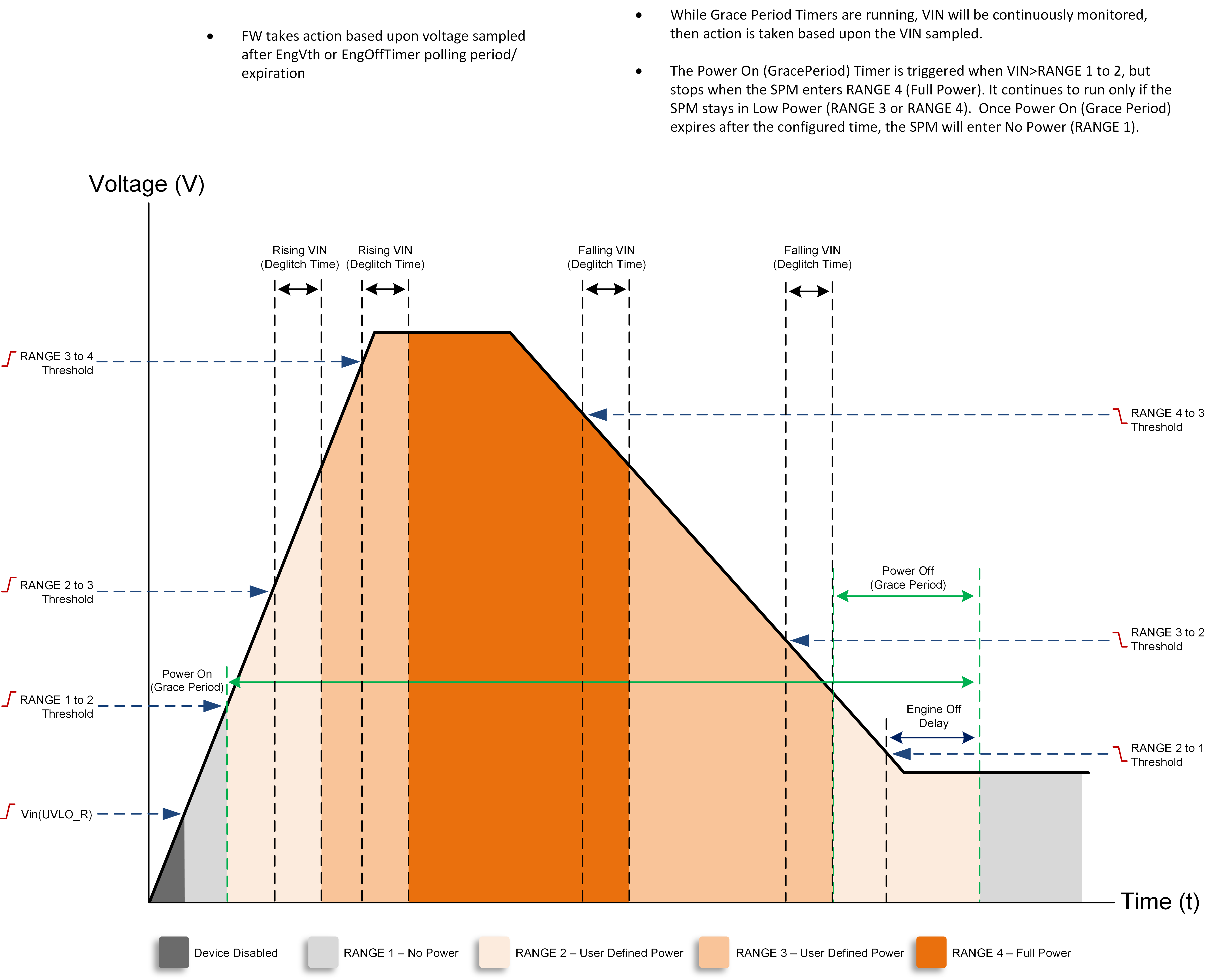
The TPS257xx-Q1 supports a dynamic port power management scheme for VIN supply voltage fluctuations in case of Engine On/Off transition events. Through dynamic detection of the supply voltage input level, the SPM takes action to enter or exit the appropriate power level. Upon detection of low VIN below normal operating range, the SPM enters a lower power mode to protect the system from overheating and excessive input current draw. The SPM also filters a fluctuation or temporary glitch on VIN to prevent an abrupt loss of USB port power which in turn enhances the end user experience. Table 4-4 and Table 4-5 show the VIN threshold and timer parameters for the TPS257xx-Q1 D version devices. All parameters are configured via the GUI except for VIN UVLO. Figure 4-5 depicts an example of how different power modes, as determined by the VIN threshold levels, work in conjunction with the deglitch filter and timers.
| VIN Threshold Parameters | Description |
|---|---|
| RANGE 3 to 4 | Full Power RANGE 4 entry threshold (for example, Engine fully ON condition with Car Key Knob in ON position) |
| RANGE 4 to 3 | RANGE 3 entry from RANGE 4 (Full Power) falling threshold (such that, Car key knob in accessory position with nominal VIN accessory mode voltage level) |
| RANGE 2 to 3 | RANGE 3 entry from RANGE 2 rising threshold |
| RANGE 3 to 2 | RANGE 2 entry from RANGE 3 falling threshold |
| RANGE 1 to 2 | RANGE 1 (No Power) to RANGE 2 (Low Power) rising threshold. This transition triggers entry into Low Power state immediately. If VIN remains above this threshold but below the RANGE 2 to 3 threshold for the Power Off Grace Period Timer duration, VBUS is disabled after the timer expiration. (for example, Car key knob in accessory position with lower VIN accessory mode voltage level) |
| RANGE 2 to 1 | No Power RANGE 1 entry threshold after Engine Off Delay expiration. (for example, Car key knob in accessory position with lower VIN accessory mode voltage level) |
| Vin(UVLO_R) | Hardware VIN UVLO voltage level. The SPM Controller is disabled. |
| Engine On/Off Timer Parameters | Description |
|---|---|
| Rising VIN Deglitch | Deglitch time to enter a higher RANGE from a lower RANGE after VIN reaches threshold. |
| Falling VIN Deglitch | Deglitch time to enter a lower RANGE from a higher RANGE after VIN reaches threshold. |
| Power On (Range 1 to 2) | Power On (Grace Period) timer. Timer starts after RANGE 2 is entered from RANGE 1. Once this timer expires and the system is still in RANGE 2, RANGE 1 will be entered and VBUS will be disabled. |
| Power Off (Range 3 to 2) | Power Off (Grace Period) timer. Timer starts when RANGE 2 is entered from RANGE 3. Once this timer expires and the system is still in RANGE 2, RANGE 1 will be entered and VBUS will be disabled. |
| Engine Off Delay | Engine Off Delay timer. Delay time to enter RANGE 1 (No Power) after VIN falls under the RANGE 2 to 1 threshold. |
 Figure 4-5 VIN Level and Engine On or Off
Power Transition
Figure 4-5 VIN Level and Engine On or Off
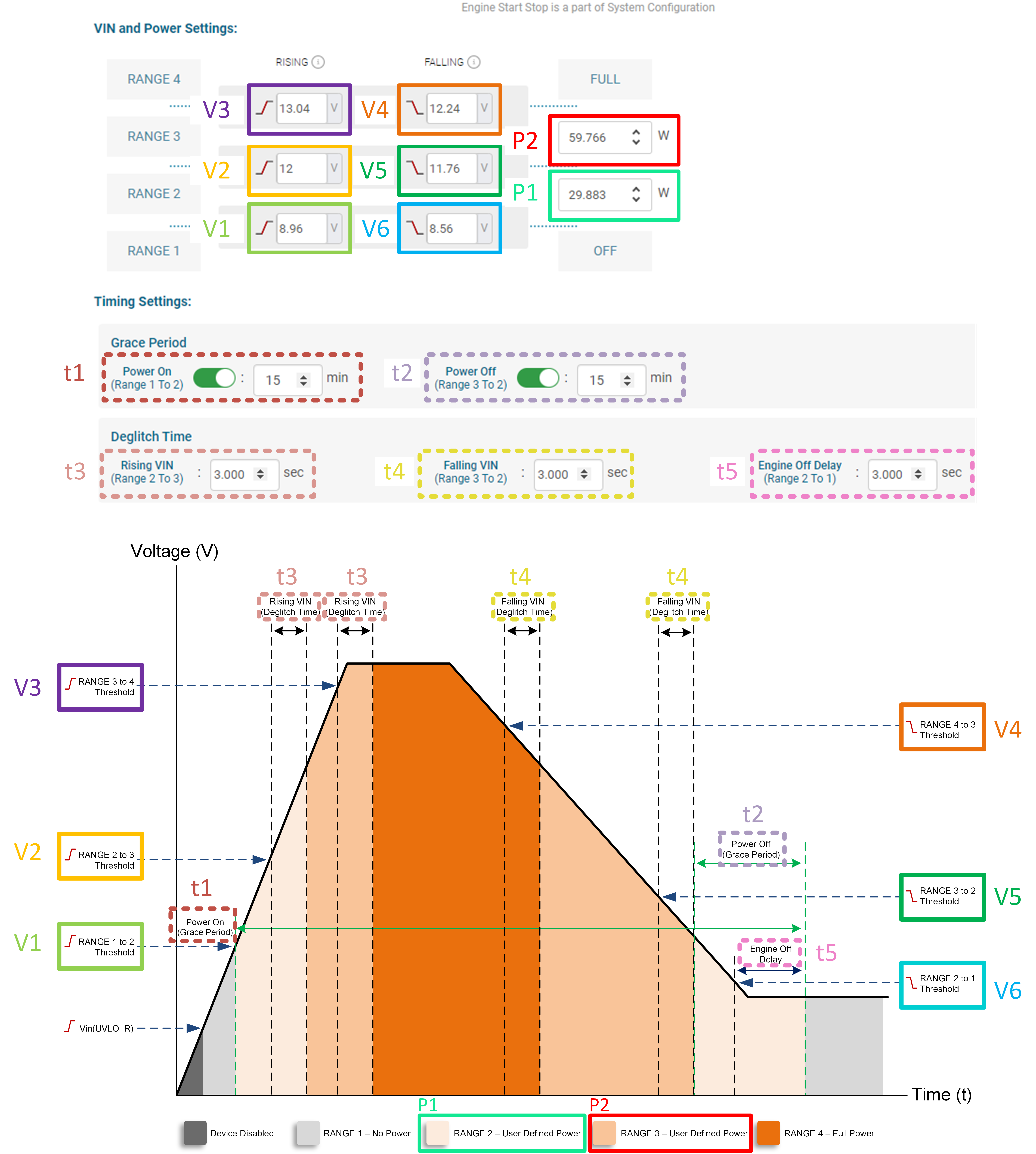
Power TransitionFigure 4-6 shows the GUI entry example in the Advanced Configuration view.
 Figure 4-6 Engine On or Off GUI Entry
Example