SLVAFG6B December 2022 – November 2024 TPS25762-Q1 , TPS25763-Q1 , TPS25772-Q1
3 Multi-Port Power Allocation Policy
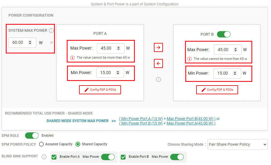
The SPM Engine, which contains the Multi-port Power Allocation Policy, is configurable using the TPS257XX-Q1-GUI. The following parameters are configured per system requirements for correct SPM operations.
Table 3-1 SPM Engine Parameters
| SPM Engine Parameters | Description |
|---|---|
| System Max Power | Total system power capacity that is allocated to all ports |
| Port Max Power | Maximum VBUS power for each port. Power contract is limited to the maximum value configured in this parameter |
| Port Min Power | Minimum VBUS power for each port. Minimum power configured in this parameter is designed for each port. |
The SPM Engine parameters can be configured from the GUI's Advanced Configuration View menu. Refer to the TPS257xx-Q1 GUI Configuration Guide for more information. Figure 3-1 shows the GUI's SPM power parameter configuration in the Advanced Configuration view.
 Figure 3-1 SPM Engine Configurable
Parameters – Advanced Configuration