SLVAFJ9 March 2023 TPSF12C1 , TPSF12C1-Q1 , TPSF12C3 , TPSF12C3-Q1
- Abstract
- 1 Table of Contents
- Trademarks
- 2 Introduction
- 3 EMI Frequency Ranges
- 4 Passive EMI Filters for High-Power, Grid-Tied Applications
- 5 Active EMI Filters
- 6 Generalized AEF Circuits
- 7 Selection of the CM Active Filter Circuit
- 8 The Concept of Capacitive Amplification
- 9 Practical AEF Implementations
- 10Practical Results
- 11Summary
- 12References
10.2 High-Voltage Testing
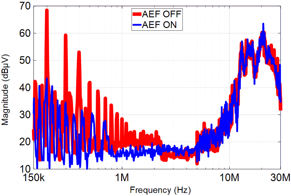
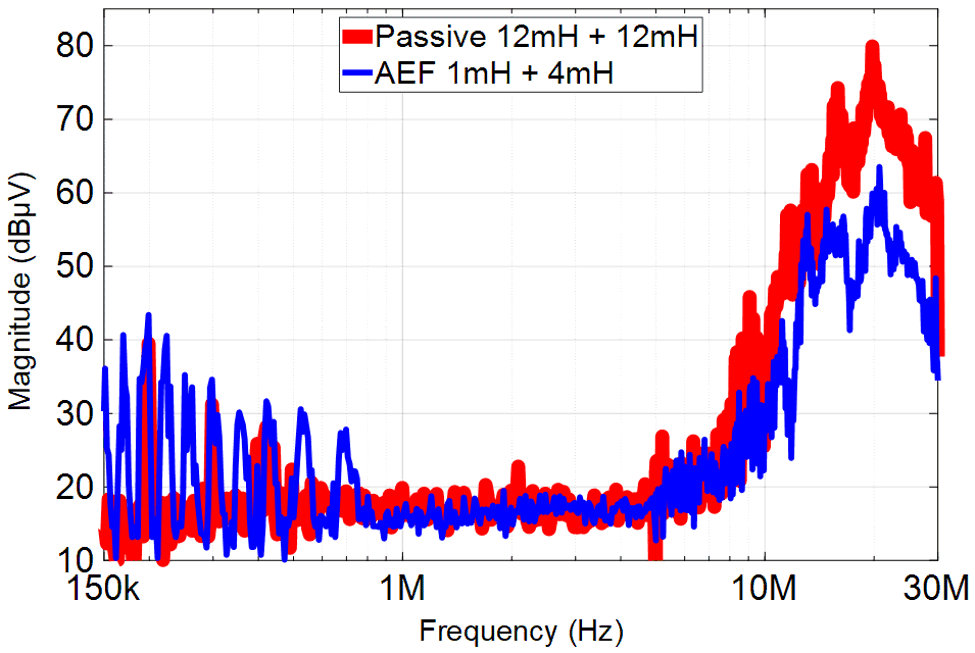
Figure 10-4 and Figure 10-5 show the measured CM EMI performance with the TPSF12C1-Q1 single-phase AEF IC using the power stage of the High-Efficiency GaN CCM Totem-Pole Bridgeless Power Factor Correction (PFC) Reference Design (TIDM-1007 shown in Figure 4-2), which is a 3.3-kW single-phase bridgeless PFC converter [3] with LMG3410 GaN power devices switching at 100 kHz.
 Figure 10-4 EMI Performance With TIDM-1007: AEF Disabled vs. Enabled Using the Same Filter
 Figure 10-5 EMI Performance with TIDM-1007: A Small-Choke AEF Design Compared to a Large-Choke Passive Filter
As evident in Figure 10-4, the AEF provides 15 to 30 dB of CM noise attenuation in the low-frequency range (150 kHz to 3 MHz), which enables a filter using 1- and 4-mH nanocrystalline chokes to achieve an equivalent CM attenuation performance as a passive filter design with two 12-mH chokes, as shown in Figure 10-5. To support a fair comparison, these chokes derive from the same component family with a similar core material (vendor: Würth Elektronik). In addition, the smaller-size chokes of the AEF-based design provide better attenuation at frequencies above 10 MHz given the lower intrawinding parasitic capacitance.
Figure 10-6 shows photos of the filters used for the EMI results presented in Figure 10-5. The AEF enables a 52% reduction in box volume of the CM chokes, as highlighted in Figure 10-7.
Table 10-1 captures the applicable parameters for the CM chokes highlighted in Figure 10-6. The AEF achieves a 60% total copper loss reduction at 10 ARMS (PCU = 6 W – 2.36 W = 3.64 W, neglecting the winding resistance increase from temperature rise), which implies lower component operating temperatures and improved capacitor lifetimes.
| Filter | CM Choke Part Number | Quantity | LCM (mH) | RDCR (mΩ) | fSRF (MHz) | Size (L × W × H, mm) | Mass (g) | PCu (W) |
|---|---|---|---|---|---|---|---|---|
| Passive | 7448051012 | 2 | 12 | 15 | 0.8 | 23 × 34 × 33 | 36 | 3.0 |
| Active | 7448041104 | 1 | 4 | 8.5 | 10 | 19 × 28 × 28 | 17 | 1.7 |
| 7448031501 | 1 | 1 | 3.3 | 40 | 17 × 23 × 25 | 10 | 0.66 |
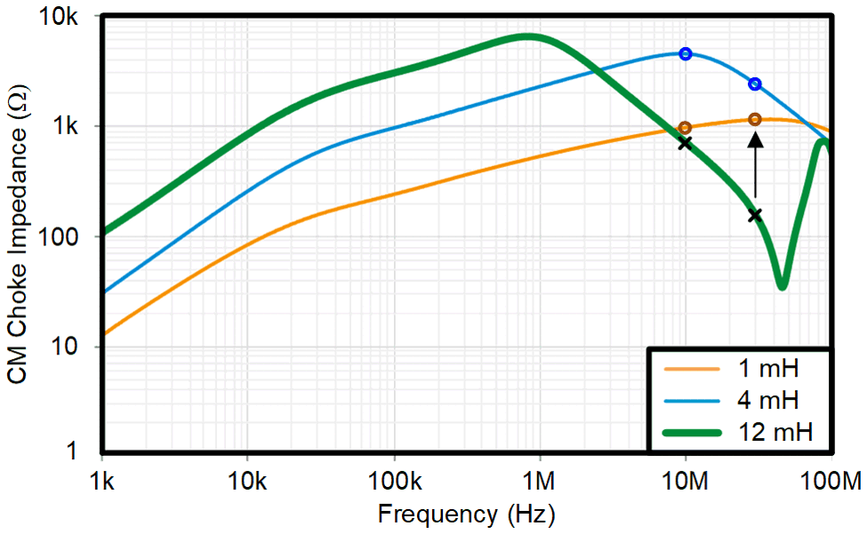
Figure 10-8 provides impedance curves for the CM chokes to highlight the smaller-size components that have a higher self-resonant frequency and improved high-frequency performance. As an example of the higher CM impedance at high frequencies because of the lower intrawinding capacitance, the impedance of the grid-side CM choke at 30 MHz increases from 150 Ω to 1.1 kΩ (when going from 12 mH in the passive design to 1 mH in the active design). The × and o markers shown at 10 MHz and 30 MHz in Figure 10-8 demarcate the respective impedances for passive and active designs. The higher choke impedance above 10 MHz for active designs largely obviates the need for grid-side Y-capacitors.
 Figure 10-8 Impedance Characteristics of the Selected CM Chokes in the Passive Design (2 × 12 mH) and Active Design (4 mH and 1 mH)
As expected, horizontally mounted chokes in three-phase circuits can generally yield even larger percentage footprint reductions relative to the vertically mounted chokes common in single-phase designs.