SLVAFM7 June 2024 TLC6983
3.2.2 Darker Coupling
Brighter coupling has been discussed in previous session. Darker coupling is easier.
Essentially, darker coupling is the opposite of the brighter coupling. Hence, the root cause is actually the same. Figure 3-23 shows the root cause analysis of the darker coupling. The electric charges from OUT1 is supposed to fully go to LED01 (and the parasitic capacitor C01) as the current path shown in red dotted line, but shared by LED00 (and the parasitic capacitor C00) as the current path shown in blue dotted line. So, LED01 looks darker than usual.
Though darker coupling has the same root cause with brighter coupling, designs are different to solve those issues. The designs are shown in Figure 3-24 and Figure 3-25.
LED01 is normally lit up as the current path shown in red dotted line. However, LED01 also sets a dummy rising one-shot on OUT0 which produces a fake one-time switch-ON for darker coupling compensation. The parasitic capacitor of LED00 is charged during the short fake switch-ON time. However, the LED is not lit up during this charge process (called dummy rising one-shot).
 Figure 3-23 Root Cause Analysis of Darker Coupling
 Figure 3-24 Analysis of Darker Coupling Elimination
 Figure 3-25 Darker Coupling Elimination by Dummy Rising One-shot
The line ceiling is used to eliminate brighter coupling and dummy rising one-shot is used to eliminate darker coupling. Why can’t only use either one to solve both issues? Actually, line ceiling can’t fully solve darker coupling due to depending on how strong the clamp circuit is. Dummy rising one-shot can not solve brighter issue and makes the issue worse since unchosen lines are floating.
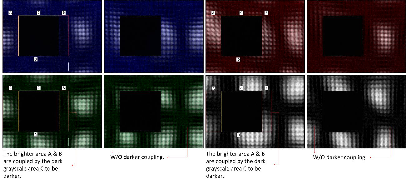
Figure 3-26 shows the comparison demo with or without darker coupling. You can see that the line ceiling circuit works very well. When enabled, we do not see coupling anymore.
 Figure 3-26 Comparison Demo With or Without Darker Coupling