SLVAFQ3 January 2024 DRV8213
Introduction
Motor stall detection is crucial for many applications and is important for several reasons. First, motor stall detection helps detect when the motor reaches end of travel or when it suddenly stops due to an obstruction. For example, a deadbolt of an electric door lock reaching the closed position causes the motor to stall. Second, stall detection can help minimize long term damage to the motor and the mechanical system from excessive heat, wear, and stress, which occurs when a motor is overdriven when stalling. Lastly, stall detection improves efficiency and reduces power consumption by avoiding unnecessary energy consumption. Some examples of applications that benefit from motor stall detection include vacuum robots, electric door locks, and portable printers.
Today, methods exist for detecting when a brushed DC (BDC) motor stalls. These include, measuring the motor current, back EMF, and using encoders and hall sensors to monitor the position of the motor. All of these methods require some level of discrete circuitry and software implementation which increases the design cost and design size of the PCB. In this application brief, a fully integrated and intelligent stall detection design is presented that can replace discrete designs. This design is integrated in TI’s latest DRV8213 motor driver.
Discrete Stall Detection Designs
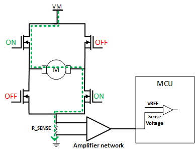
One of the most common methods for detecting stall in a BDC motor is by measuring the motor current. The motor current is measured using a sense resistor in series with the motor current path. The sense resistor generates a voltage across the motor that is proportional to the motor current. This sense resistor voltage is fed into an amplifier network to boost the voltage to be within the ADC dynamic range of the MCU. The MCU monitors the current sense output and detects when the current exceeds a certain threshold (VREF). When a BDC motor stalls, the current increases significantly. The threshold must be set higher than the steady state current and must be experimentally determined for the specific motor and application.
When the sense voltage exceeds VREF, a stall is detected and the MCU can perform the desired response, such as stopping the motor, reversing motor direction, or alerting the user. Figure 1 shows a high-level block diagram for this design.
 Figure 1 Current Sensing Based Stall
Detection Block Diagram
Figure 1 Current Sensing Based Stall
Detection Block DiagramThe threshold value (VREF) depends on the specific motor and application. Experiments with different values and operating conditions can be required to find the threshold that covers worst cases such as when the motor is fully loaded or when operating at high or low temperatures. The sense resistor must be rated for the maximum current expected in the system.
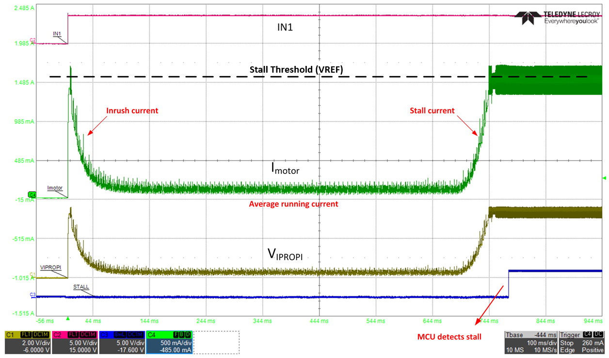
BDC motors have high inrush currents during startup due to the high torque required to overcome moments of inertia to begin spinning. Therefore, the MCU must ignore the current during the inrush period to avoid false stall detection. This can be achieved by simply adding a delay or blanking time from when the threshold is exceeded to when the MCU reports the stall condition. The delay time is experimentally determined for each motor and application. Figure 2 shows this design using a real motor from start-up to a stall condition.
 Figure 2 Waveform of Motor from
Start-up to Stall
Figure 2 Waveform of Motor from
Start-up to StallDRV8213 Integrated Stall Detection
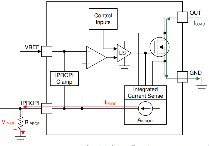
The DRV8213 integrates a stall detection method that relies on constant current monitoring similar to the discrete design mentioned in the previous section. The integrated current sensing on the DRV8213 has a current output that is proportional to the motor current. This proportional current is called IPROPI. Figure 3 shows the current sensing and regulation block of the DRV8213. The integrated current sense block is a current mirror circuit with the scalar factor. The scaled down current flows through an external resistor generating the voltage. This voltage is compared to an external VREF voltage. The VREF voltage has two purposes in the DRV8213. The VREF voltage is used to set the current regulation limit and the stall detection limit. Once the exceeds, stall detection is detected by the driver if it has been enabled.
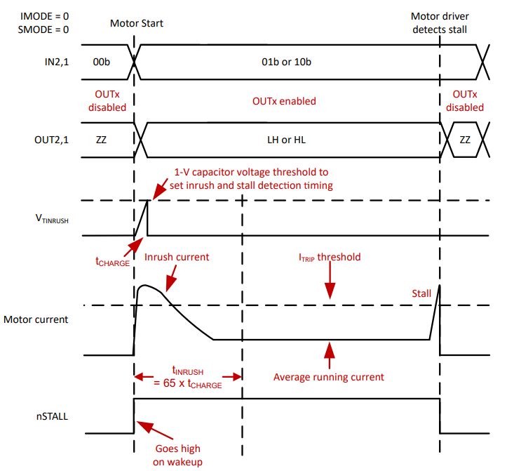
The DRV8213 addresses the false stall detection problem during start-up by including an adjustable blanking time, TINRUSH. The DRV8213 has a TINRUSH pin where an external capacitor (CINRUSH) can be connected to GND. This pin sets the amount of time that the stall detection scheme ignores the inrush current during motor start-up. The is shown by the formula: TINRUSH = 6.5x10⁶ * CINRUSH
 Figure 3 Integrated Current Sensing
Block Diagram
Figure 3 Integrated Current Sensing
Block DiagramFigure 4 shows more information regarding the stall detection operation. The inrush current is regulated to the ITRIP threshold. The stall detection scheme ignores this inrush current for a time set by TINRUSH. Once the motor stalls, the current rises again and this time the driver flags a stall detection by setting the nSTALL pin logic LOW to indicate a stall is detected.
 Figure 4 DRV8213 Integrated Stall
Detection Operation Diagram
Figure 4 DRV8213 Integrated Stall
Detection Operation DiagramThe driver has three response settings for when a stall has been detected. The setting is set by the SMODE pin. The settings are as follows:
- Latched disable with indication: the OUTx pins disable and the nSTALL pin pulls low.
- Indication only: the OUTx pins remain active and the nSTALL pin pulls low.
- Indication only: the OUTx pins remain active and the nSTALL pin pulls low. Device uses internal VREF (510 mV) for stall detection.
The third setting is to be used in the case that providing external voltage to the VREF pin is not possible or not desired. The internal reference voltage is fixed at 510 mV.
To conclude, the advantages of the DRV8213 design are lower overall design cost and PCB design size because the design is fully integrated to the IC. The small footprint free some space on the PCB allowing for more features to be added or to minimize the PCB size for size constrained applications. The built-in intelligence (such as the TINRUSH blanking time and the programmable stall detection response) eliminates the need for an external MCU. To learn more about the DRV8213, visit the DRV8213, product page.