SLVAFR4 February 2024 TPS25762-Q1 , TPS25763-Q1 , TPS25772-Q1
4.4 SPT.6 PPS Voltage Step Test
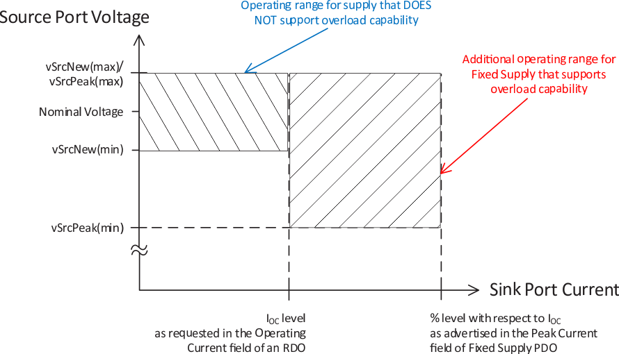
 Figure 4-5 PPS Positive Voltage Transitions
For PD products supporting PPS function or advertising APDO capabilities, SPT.6 shall be tested. The PPS Step Test verifies that when a source port makes a contract using an APDO, the output follows the monotonicity and tolerance requirements from USB PD spec section 7.1.4.3. The test is required to pass no matter for single port or multi-ports and is verified by Quadramax instrument. For multi-ports tests, two or more Quadramax instruments are needed. For bench set-up details, please refer to ‘QuadraMAX PPS Test Guide.
During tests, SPT verifies several tolerance requirements based on PD spec. In practice, error ‘The source voltage remains within vPpsValid for the duration of the transition’ usually occurs. Just open the log folder and search ‘testLog.csv’ file. The file logs all test data information of each step. Step 2.k.1.b.ii shows failure. Check ‘Universal Serial Bus Type-C and Power Delivery Source Power Requirements Test Specification’ and the spec also describes the failure step details.
To show the log more intuitively, checking both total-phase data log and QuadView data log is a good practice. Download both tools from total-phase official website and USBIF official website individually. Both methods depict logs by waveforms. Acquiring total-phase data log is strongly recommended. Customers can require test institutions to extract data by total-phase tools. The data log is beneficial for data analysis further. Institutions opt to not use these tools.
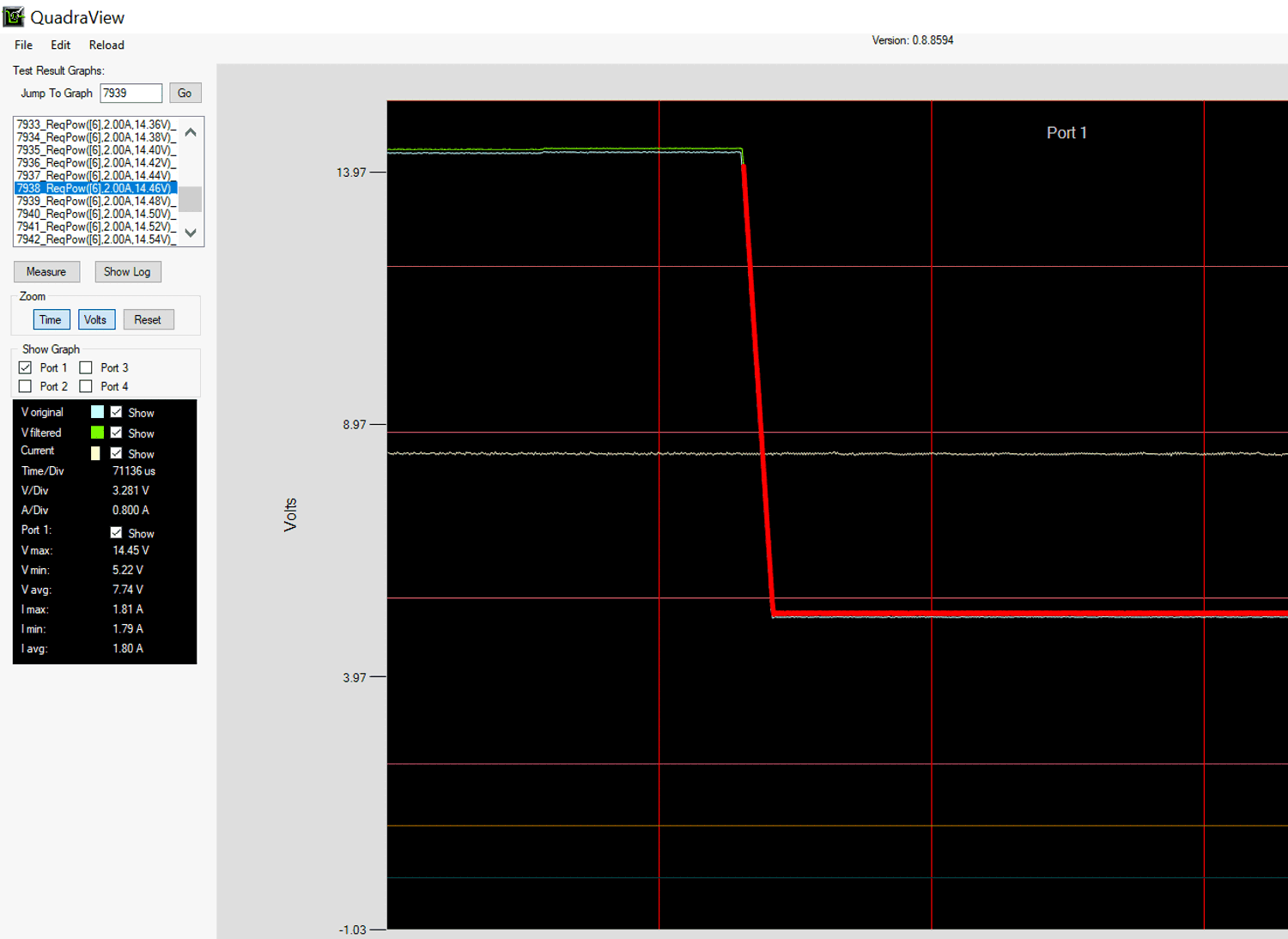
 Figure 4-6 QuadView Data Log Check
Check picture #7939 by QuadView, red line indicates the error. The data log shows as voltage increases from 14.46V to 14.48V by 20mV step, VBUS voltage drops to 5V.
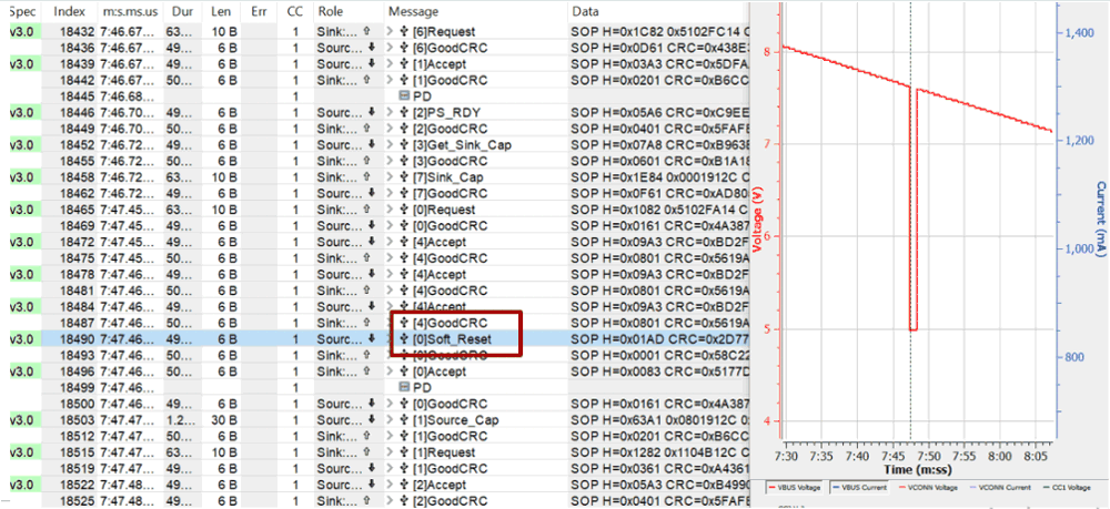
 Figure 4-7 Total-Phase Data Log Check
To spot the root cause further, check total-phase data log. The log shows Soft_Reset occurs. By comparison test in lab, the error is introduced by tester issue. Update latest tester software version, issue solved.