SLVAFR4 February 2024 TPS25762-Q1 , TPS25763-Q1 , TPS25772-Q1
5 Analysis of Some Failure Examples
Common check failure
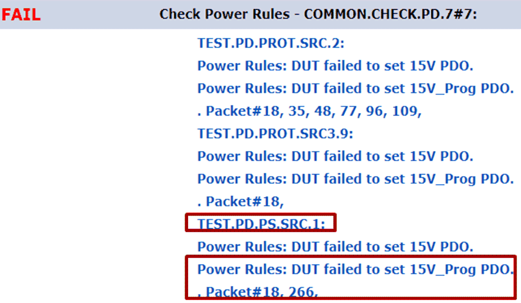
Open .XML format log file and spot the failure item. The log shows Common.Check.PD.7#7 failure and occurs as testing TEST.PD.PS.SRC.1.
 Figure 5-1 Common Check Data Log
 Search CTS file and locate Common.Check.PD.7#7. ‘The Tester compares all PDOs to VIF field PD_Power_as_Source and checks that they meet the requirements of the Power Rules.’ The line indicates PDOs settings contradict with PD_Power_as_Source in VIF.
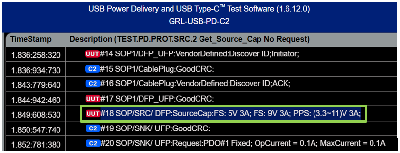
Open the failure .grltrace file and based on Figure 5-2, spot packet #18 in the data log. VIF settings contains 5V 3A, 9V 3A and (3.3V~11V) 3A. Also check field PD_Power_as_Source = 33W. The failure prompts DUT failed to set 15V_Prog PDO. So the failure is caused due to incorrect PD_Power_as_Source setting. Fill in 27W which is determined by Fixed PDO power instead of APO power. What’s more, Product_Total_Source_Power is 27W as well.
 Figure 5-2 TEST.PD.PRO.SRC.2 Data Log by GRL-C2
 TEST.PD.PROT.SRC.2#2 Get_Source_Cap No Request
Open .XML format log file and spot the failure item. The item belongs to protocol layer failure and occurs as testing DUT source capability.
 Figure 5-3 XML Data Log
Look up CTS file and search Get_Source_Cap No Request test item. The Tester sends a Get_Source_Cap Message to the UUT. After receiving a Source_Capabilities Message, the Tester intentionally does not send the Request Message to force a SenderResponse Timer timeout on the Source UUT. The Tester verifies correct implementation of this timer.
Open the failure item .grltrace or Lecroy .usb log file and find index 37 based on Figure 5-4. Before further analysis, get noted that the Code ‘Rev3ChkdSrc’ means that the Port is being tested for PD Revision 3, with the Tester set not to support Unchunked Extended Messages, and as a Source. ‘Rev2Src’ suggests the Port is being tested for PD Revision 2 and as a source. So both check PD2.0 specification and PD3.1 specification. Listed as below. The log shows very clear that PD3 mode passed but PD2 mode fail. Because it’s a firmware failure, so ask firmware team for one new patch and solve this issue.
 Figure 5-4 GRL-C2 data log of TEST.PD.PRO.SRC.2
TEST.PD.PS.SRC.1 Multiple Request Messages
Open .XML format log file and spot the failure item. The failure belongs to Power Source layer and occurs as testing DUT source capability.
The purpose of this test is to check whether DUT Source responds correctly to various Sink load Request Message. VBUS voltage shall be limited in provided range during Request transition. Open the failure log file .XML. The failure occurs as current increases from 2.25A to 3A. Measured VBUS voltage is out of range. Protocol log shows the failure happens at the place of index 81.
 Figure 5-5 XML data log of TEST.PD.PS.SRC.1
Further, check the data log .grltrace or LeCroy .usb file. Spot packet 81. The packet indicates requested operating current is 3A. Waveforms log shows more clearly of the process. By initial analysis, the issue is related to cable compensation deficiency. After improving cable compensation level, test passes.
 Figure 5-6 GRL-C2 Log of TEST.PD.PS.SRC.1
During compliance test procedures, various issues or concern shall encounter. Above 3 cases are some general analysis process. Additionally, some failures are tester issues instead of being introduced by products or silicon. Furthermore, due to continuous updates of PD specification or PD compliance test specification, some tests can be waived. Please ask USB-IF for waiver if necessary. Refer to references for more details.