SLVAFR4 February 2024 TPS25762-Q1 , TPS25763-Q1 , TPS25772-Q1
2.2 Generate VIF Manually
Below is the general view of VIF editor shared by USB-IF. Customers or engineers can download the tool on USB-IF official website. The tool allows engineers to configure needed parameters matching with product waiting for test. The editor generates .xml VIF for Type-C compliance, PD compliance, USB3.2 compliance and USB4 compliance. The following sections depict these fields and features briefly based on products TPS2772-Q1. Single port PD devices have a similar principle. Open VifEditor which can be downloaded from USBIF official website. Firstly, choose Port Product and then create new VIF. Below tab emerges.
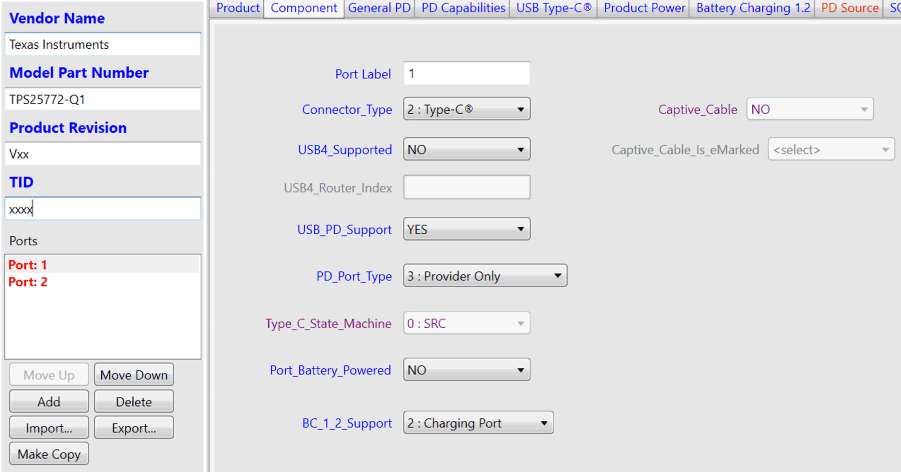 Figure 2-1 Generate VIF Manually
Captive_Cable:
Indicates whether this Component has a captive cable. Any Component that presents a Type-A or USB Type-C plug is considered to have a captive cable, even if there is nothing visible that looks like a cable (for example, a USB thumb-drive).
PD_Port_Type:
3 - Provider Only (asserts Rp)
TPS257xx-Q1 only serves as a power source. So item 3 ‘Provider Only’ must be chosen.
As the above information is filled in, other tabs pop up.
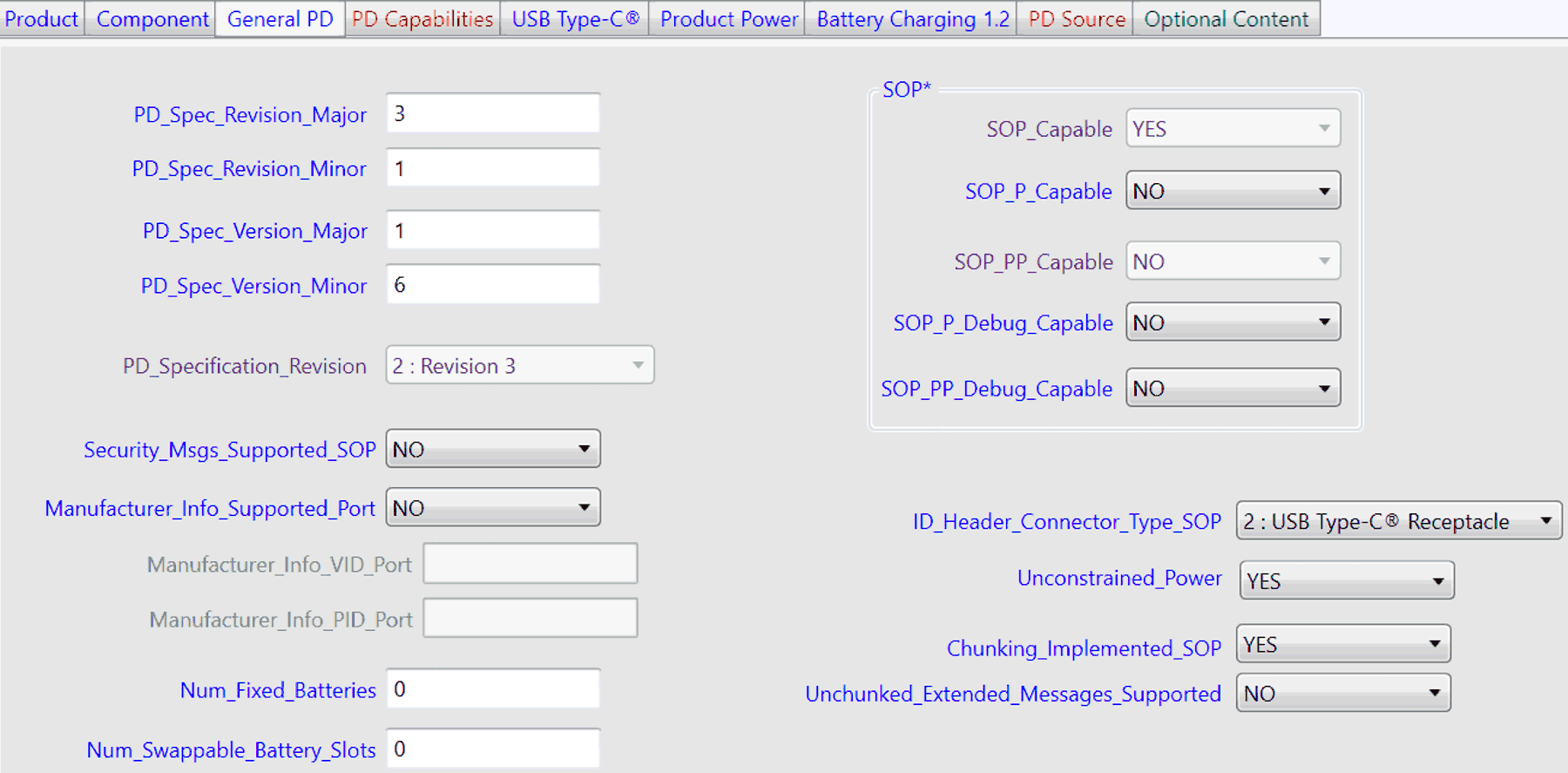 Figure 2-2 General PD Configuration
For PD_Spec_Version_Minor, please check USBIF official website for the latest version number.
Note that PD CTS revision 1.2 is the initial merged specification. This document specifies USB-IF compliance tests for a USB PD3.1 device. This document includes both PD2.0 and PD3.0 test items into one specification. Products must pass both PD2.0 and PD3.0 items test. Customers need to pay attention to the latest specification versions no matter for PD CTS or PD specification. USBIf can modify, add, remove, relax or strict some items. The updates matters a lot of the test results. Please check USB IF official website timely for the latest specifications.
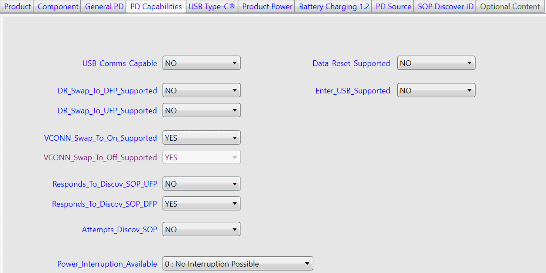 Figure 2-3 PD Capabilities
USB_Comms_Capable:
This item signifies whether Qualifying Product is capable of enumerating as a USB host or device?
Generally, this is no meaning the product does not support data communication and only acts as power source. But some customers, can bypass IC data line and connect USB2.0 or USB3.2 signals directly to HUB or SOC to support data communication. For this scenario, check Yes for this item. The reason is that tester checks data line signals to confirm whether any signal passes or not.
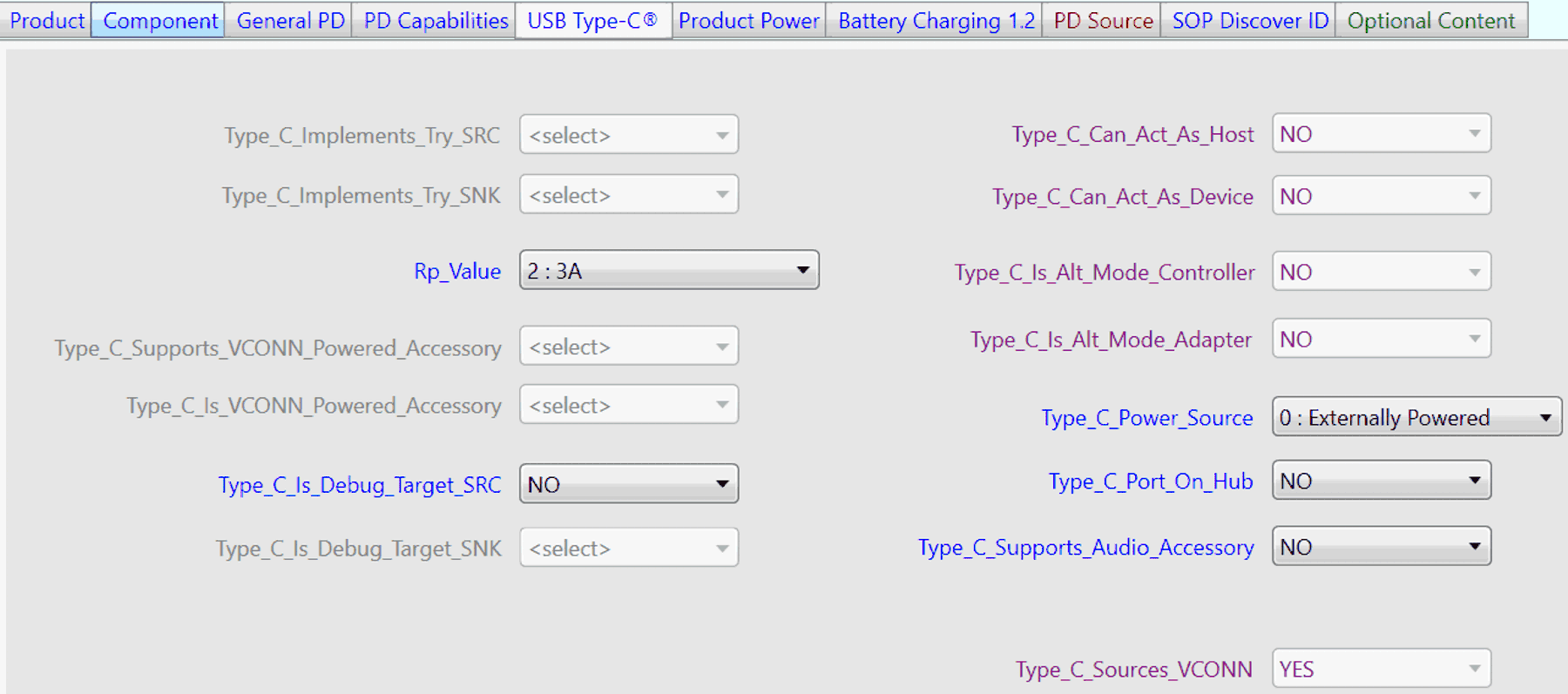 Figure 2-4 USB Type-C Configuration
Additionally, based on Vendor Info File Definition, if USB_Comms_Capable is No, then Type_C_Can_Act_As_Host and Type_C_Can_Act_As_Device is No. If USB_Comms_Capable is set to YES and Type_C_Can_Act_As_Device is set to NO, then Type_C_Can_Act_As_Host field shall be set to YES.
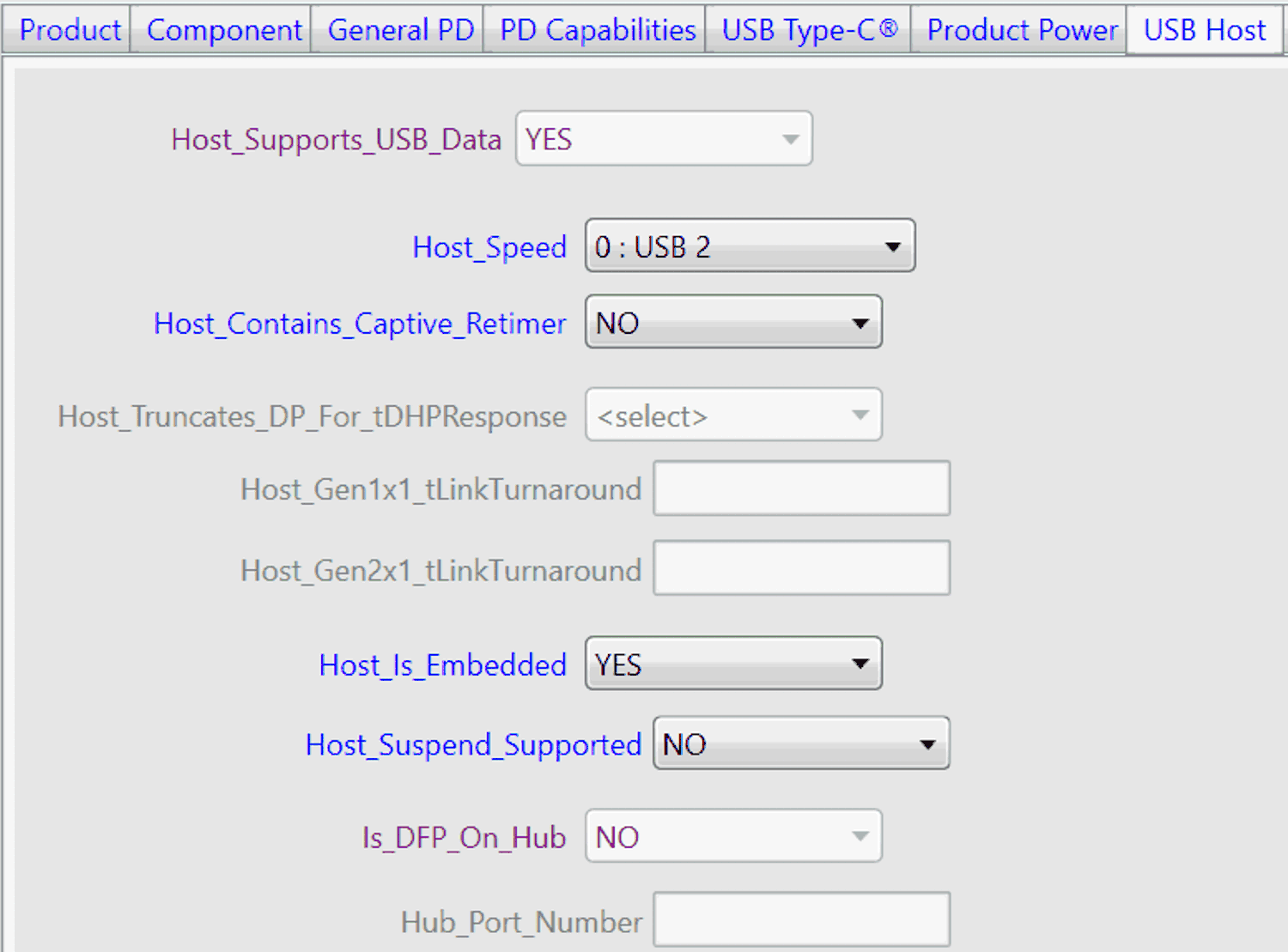 Figure 2-5 USB Host Configuration
If USB_Comms_Capable is set YES, then another panel USB HOST pops up. Please configure the page according to Figure 2-5.
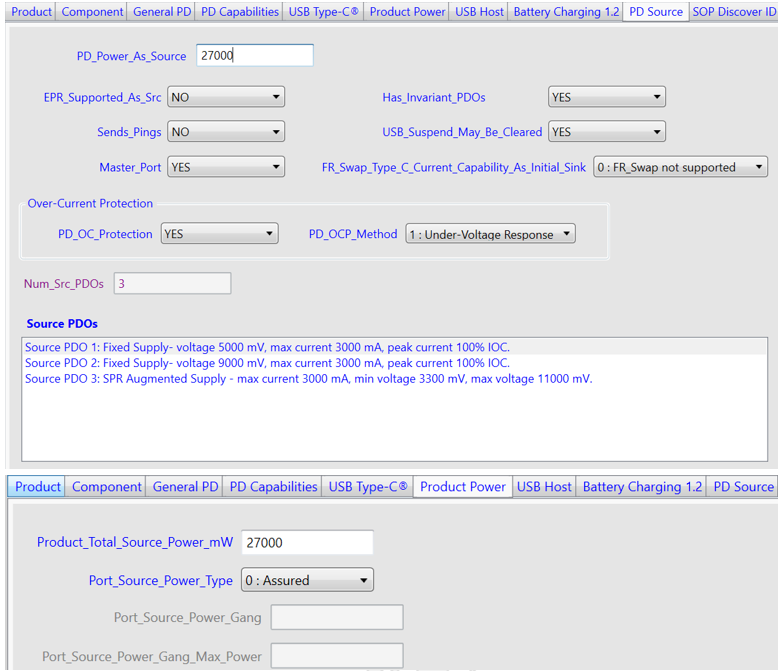 Figure 2-6 PD Source Configuration
Figure 2-6 sets parameters of PD source. Note that PD_Power_As_Source is fixed Power Delivery Objects (PDO) maximum power instead of Augmented Power Delivery Objects (APDO). Otherwise, some failures can occur as doing PD compliance test. So for above case, fill in 27W source power other than 33W. Also Product_Total_Source_Power_mW also corresponds to 27W. Port_Source_Power_Type is determined by customer’s specific requirements.
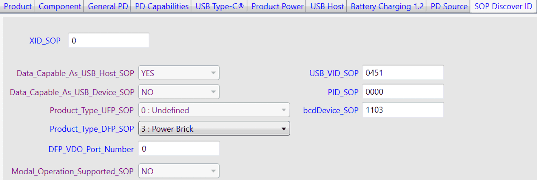 Figure 2-7 BC1.2 Protocol and SOP Discover ID
For XID_SOP, A decimal number assigned by USB-IF prior to certification. For USB_VID_SOP, this field is a 4-digit hexadecimal number, with valid values in the range of 0h - FFFFh (0 - 65535). This field is assigned to the Vendor by USB-IF. The vendor must ask USBIF and apply for both XID and VID before informal compliance certification or test.
For BC_1_2_Charging_Port_Type, the application generally is charge only. Item 0, DCP mode can be chosen. Some customers can require to support data communication. So for BC1.2 charging protocol, item 1, CDP mode is the choice.
Above is the general configuration of VIF parameters. Some parameters or panels can change in future based on specification revision updates or modification by USB IF. Please check and download the latest spec or configuration tools on USB IF official website.