SLVAFR4 February 2024 TPS25762-Q1 , TPS25763-Q1 , TPS25772-Q1
4.1 SPT.1 Load Test and SPT.2 Capabilities Test
 Figure 4-1 Fixed Supply Voltage Transition
Figure 4-1 shows fixed supply voltage transition tests which asserts in PD CTS Power Supply section 7.1.4.1. The Source Shall transition VBUS from the starting Voltage to the higher new Voltage in a controlled manner. The negotiated new Voltage (For example, 5V, 9V, 15V…) defines the nominal value for vSrcNew. During the transitions, voltage thresholds and time specs shall be in demanded range.
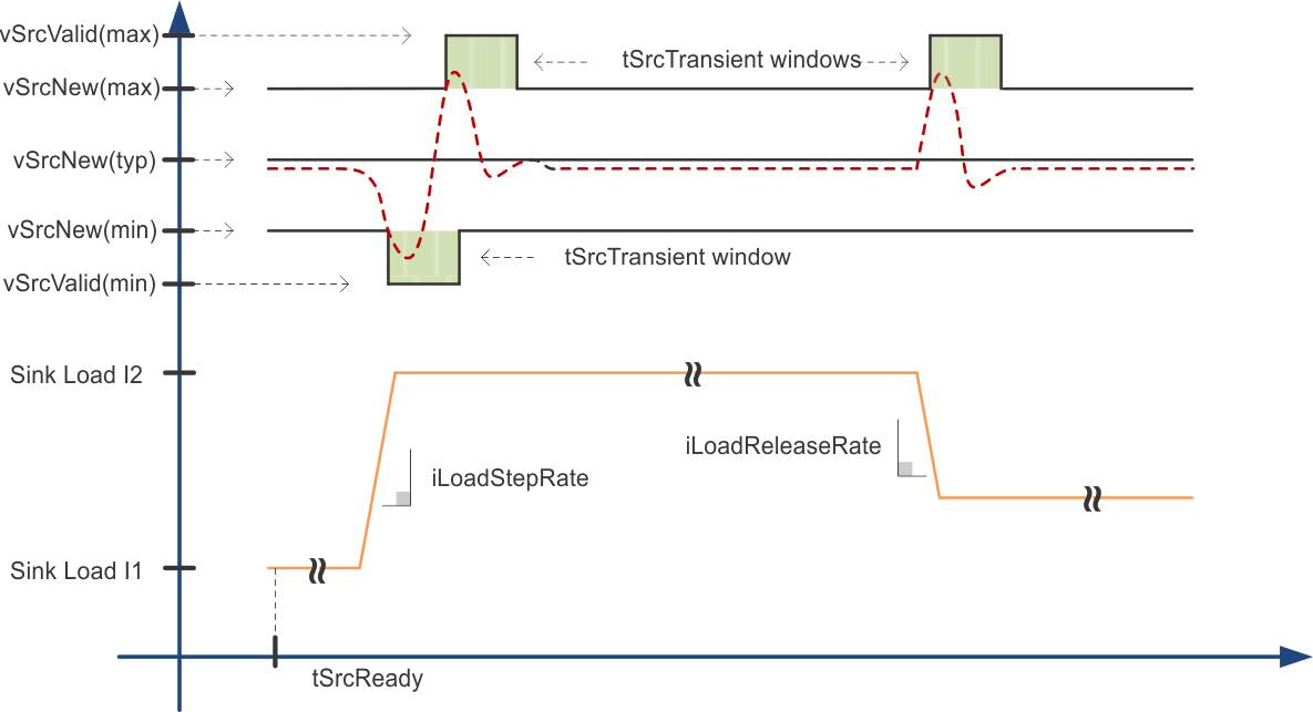
 Figure 4-2 Application of vSrcNew and vSrcValid Limits After tSrcReady
Figure 4-2 illustrates PD CTS Power Supply section 7.1.8. This test item defines output voltage tolerance and range after voltage transition is complete and during static load conditions or transient load conditions. Please refer to PD spec for more information.
SPT.2 Capabilities Test verifies that each port can simultaneously provide a different advertised voltage. This test is required for Multi-Port products with at least one PD port that supports more than one Source Capability. The test also asserts PD3.0 7.1.4.1 and 7.1.8.