SLVAFT0 July 2024 DRV8706-Q1 , DRV8714-Q1 , DRV8718-Q1
2.2 Pulse Width Modulation
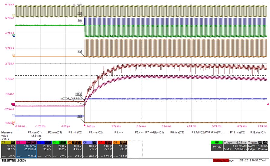
If pulse-width modulation (PWM) is used to control the effective motor voltage, the bulk capacitance on the motor supply becomes even more important. Otherwise the current variation during PWM operation can cause voltage ripple which can propagate throughout the system, causing electromagnetic interference with other components. Figure 2-2 shows typical waveforms in a motor drive system with PWM at 20kHz. The red trace marked MOTOR CURRENT shows the effect of rising current as the motor is activated, with ripple current corresponding to the PWM frequency.
 Figure 2-2 Typical Waveforms in a PWM
Motor Drive, From DRV8718-Q1 Data Sheet
Figure 2-2 Typical Waveforms in a PWM
Motor Drive, From DRV8718-Q1 Data SheetIn this example, the scale is 1A per major division of the current trace, so the variation in motor current is on the order of 200mA due to the PWM switching. This is approximately 10% of the peak motor current of about 2 amps.