SLVAFT0 July 2024 DRV8706-Q1 , DRV8714-Q1 , DRV8718-Q1
1 Introduction
Direct current (DC) motors are found in a wide variety of applications in automotive, industrial, and consumer products. When switched on or off, including during pulse-width modulation (PWM) operation, the motor current can change significantly. These current changes can create issues such as supply voltage variations and electromagnetic interference for nearby electronics.
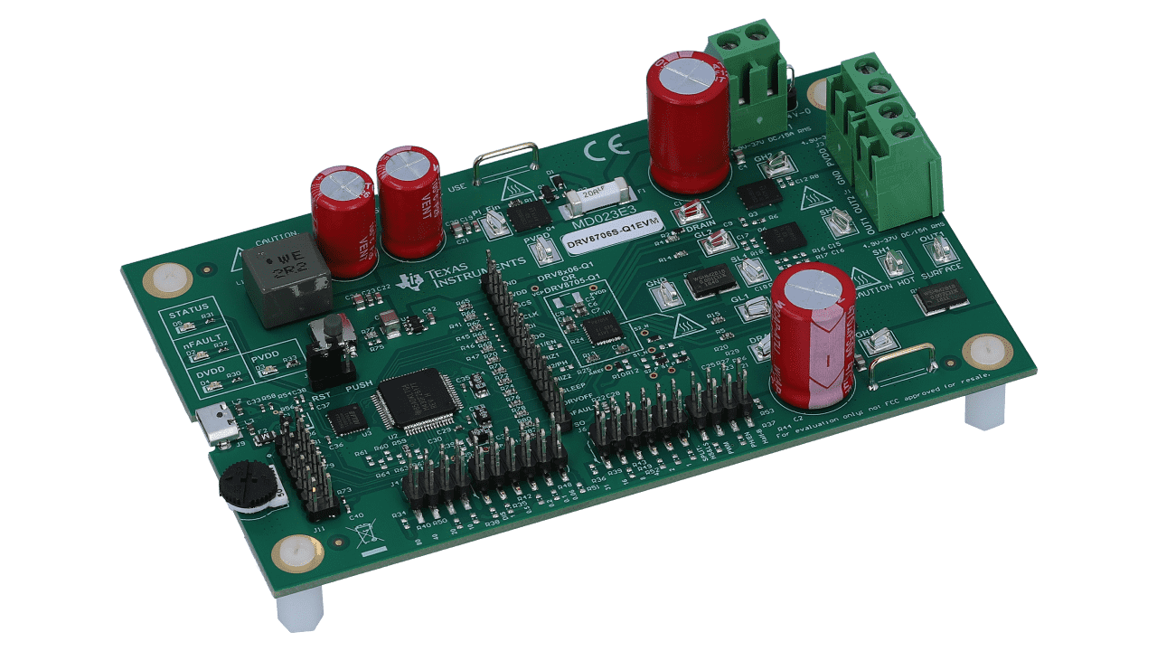
It is common to include large bulk capacitors as part of the motor driver design. These bulk capacitors act as a local reservoir of electrical charge to smooth out the motor current variation. Figure 1-1 shows a typical evaluation board with the two large electrolytic capacitors on the right side of the board acting as bulk capacitors for the DC motor driver.
Designers look for guidance on the appropriate values of bulk capacitance. In the following discussion, we can look for methods to select a proper value of capacitance based on knowledge of the motor and driver parameters. The nomenclature is based on brushed DC motors, but the same principals apply to other types, including brushless DC (BLDC) and stepper motors.
 Figure 1-1 Typical Motor Driver Board
Showing Large Bulk Capacitors