SLVAFT1 September 2024 TPS92633-Q1
2.2.2.1 Implementation Results
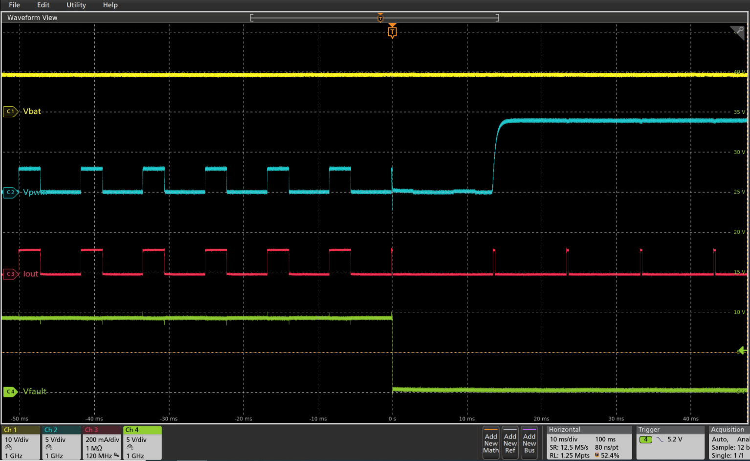
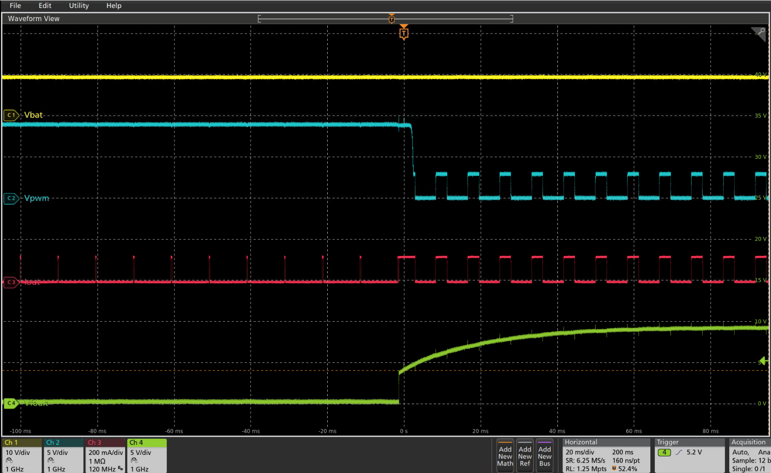
The application results with the recommended circuit implemented is shown in Figure 2-5 and Figure 2-6. Table 2-1 shows the components values.
| R1 | R2 | R3 | R4 | R5 | C1 |
|---|---|---|---|---|---|
| 100kΩ | 10kΩ | 100kΩ | 100kΩ | 100kΩ | 1uF |
 Figure 2-5 Parallel Channels Exposed to SIngle-LED-Short
Condition Detection
 Figure 2-6 Parallel Channels Exposed to Single-LED-Short
Condition Auto-Recovery
Figure 2-6 Parallel Channels Exposed to Single-LED-Short
Condition Auto-RecoveryFor a supply voltage of 10V, and 5V PWM pulse of 120Hz at 35% duty cycle, if a single-LED-short fault occurs, the FAULT pin is pulled down internally, then the PWM pins are pulled low. After a time interval of 13ms, the PWM pins are pulled up until the fault is removed. The FAULT pin is released and the output current can recover to normal operation.
Step 3: Use a MCU to Sync All Retry Currents
If a MCU is available in this system and can be used to control the PWM pins and the FAULT pin, it is easy to achieve this retry current synchronization, which can be seen in Figure 2-7. The same functionally can be achieved as the retry current sync circuit above.
 Figure 2-7 MCU Connection for TPS92633-Q1 Parallel Channels