-
TLV62095 Pin Failure Mode Analysis (Pin FMA)
TLV62095 Pin Failure Mode Analysis (Pin FMA)
Overview
This document contains the Pin failure mode analysis (pin FMA) information for the TLV62095.
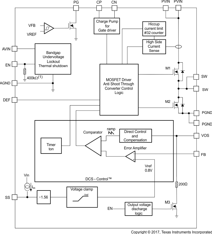
Figure 1 shows the device functional block diagram.
 Figure 1 Functional Block Diagram
Pin Failure Mode Analysis (Pin FMA)
This section provides a failure mode analysis (FMA) for the pins of the TLV62095. The failure modes covered in this document include the typical pin-by-pin failure scenarios:
- Pin short-circuited to ground (see Table 2)
- Pin open-circuited (see Table 3)
- Pin short-circuited to an adjacent pin (see Table 4)
- Pin short-circuited to VIN (see Table 5)
Table 2 through Table 5 also indicate how these pin conditions can affect the device as per the failure effects classification in Table 1.
| Class | Failure Effects |
|---|---|
| A | Potential device damage that affects functionality. |
| B | No device damage, but loss of functionality. |
| C | No device damage, but performance degradation. |
| D | No device damage, no impact to functionality or performance. |
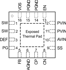
Table 2 is showing the TLV62095 pin diagram. For a detailed description of the device pins, see the Pin Configuration and Functions section in the TLV62095 4-A High Efficiency Step Down Converter with DCS-Control Data Sheet.
 Figure 2 Pin Diagram
The exposed thermal pad is connected to AGND.
Following are the assumptions of use and the device configuration assumed for the pin FMA in this section:
- The device is operating in the typical application, see the Applications section on the first page in the TLV62095 4-A High Efficiency Step Down Converter with DCS-Control Data Sheet.
| Pin Name | Pin No. | Description of Potential Failure Effect(s) | Failure Effect Class |
|---|---|---|---|
| SW | 1, 2 | Potential internal device damage | A |
| DEF | 3 | Incorrect device functionality due to different switching frequency | B |
| PG | 4 | No impact on device | D |
| FB | 5 | Incorrect device functionality due to missing feedback path | B |
| AGND | 6 | Intended connection | D |
| CP | 7 | Potential impact on device reliability; potential internal device damage | A |
| CN | 8 | Potential impact on device reliability; potential internal device damage | A |
| SS | 9 | Incorrect device functionality; Device does not start up | B |
| AVIN | 10 | Potential damage | A |
| PVIN | 11, 12 | Potential damage | A |
| EN | 13 | Device disabled | D |
| PGND | 14, 15 | Intended connection | D |
| VOS | 16 | Reduced transient performance; no output discharge available; reduced current limit | B |
| Pin Name | Pin No. | Description of Potential Failure Effect(s) | Failure Effect Class |
|---|---|---|---|
| SW | 1 | Increased current through pin (2); potential impact on device reliability; potential damage | A |
| SW | 2 | Increased current through pin (1); potential impact on device reliability; potential damage | A |
| DEF | 3 | Incorrect device functionality due to different switching frequency | B |
| PG | 4 | Intended operation if PG not used | D |
| FB | 5 | Incorrect device functionality due to missing feedback path | B |
| AGND | 6 | Incorrect device functionality due to missing AGND connection | B |
| CP | 7 | Incorrect device functionality | B |
| CN | 8 | Incorrect device functionality | B |
| SS | 9 | Intended operation; sets minimum soft start time (typ 50us) | D |
| AVIN | 10 | Device not functional | B |
| PVIN | 11 | Increased current through pin (12); potential impact on device reliability; potential internal device damage | A |
| PVIN | 12 | Increased current through pin (11); potential impact on device reliability; potential internal device damage | A |
| EN | 13 | Intended operation; internal pull-down keeps this pin low; device disabled. | D |
| PGND | 14 | Increased current through pin (15); potential impact on device reliability; potential internal device damage | A |
| PGND | 15 | Increased current through pin (14); potential impact on device reliability; potential internal device damage | A |
| VOS | 16 | Reduced transient performance; no output discharge available; potentially reduced current limit | B |
| Pin Name | Pin No. | Shorted to | Pin No. | Description of Potential Failure Effect(s) | Failure Effect Class |
|---|---|---|---|---|---|
| SW | 1 | SW | 2 | Intended connection | D |
| SW | 2 | DEF | 3 | Potential internal device damage through potential violation of abs max voltage rating of pin (3) | A |
| DEF | 3 | PG | 4 | Potential internal device damage through potential violation of abs max voltage rating of pin (3) | A |
| PG | 4 | FB | 5 | Incorrect device functionality due to disturbed feedback path; potential internal device damage through potential violation of abs max voltage rating of pin (5) | A |
| FB | 5 | AGND | 6 |
Incorrect device functionality due to missing feedback path. |
B |
| AGND | 6 | CP | 7 | Potential impact on device reliability; potential internal device damage | A |
| CP | 7 | CN | 8 | Incorrect device functionality; potential impact on device reliability | A |
| CN | 8 | SS | 9 | Incorrect device functionality | B |
| SS | 9 | AVIN | 10 | Sets minimum soft start time (typ 50us) | B |
| AVIN | 10 | PVIN | 11 | Potentially incorrect device functionality due to increased disturbance of AVIN supply by ringing on PVIN pin | B |
| PVIN | 11 | PVIN | 12 | Intended connection | D |
| PVIN | 12 | EN | 13 | Intended connection; device is enabled with VIN>UVLO | D |
| EN | 13 | PGND | 14 | Intended operation; device disabled. | D |
| PGND | 14 | PGND | 15 | Intended connection | D |
| PGND | 15 | VOS | 16 | Output short to ground, device not functional | B |
| VOS | 16 | SW | 1 | Incorrect device functionality | B |
| Pin Name | Pin No. | Description of Potential Failure Effect(s) | Failure Effect Class |
|---|---|---|---|
| SW | 1, 2 | Potential internal device damage | A |
| DEF | 3 | Intended operation; nominal switching frequency set to 1.4MHz | D |
| PG | 4 | Potential internal device damage | A |
| FB | 5 | Incorrect device functionality due to missing feedback path. | B |
| AGND | 6 | Internal damage | A |
| CP | 7 | Potential impact on device reliability; potential internal device damage | A |
| CN | 8 | Potential impact on device reliability; potential internal device damage | A |
| SS | 9 | Sets minimum soft start time (typ 50us) | D |
| AVIN | 10 | Intended connection | D |
| PVIN | 11, 12 | Intended connection | D |
| EN | 13 | Intended operation; device always enabled | D |
| PGND | 14, 15 | Potential damage | A |
| VOS | 16 | Potential internal device damage | A |
Trademarks
All trademarks are the property of their respective owners.
IMPORTANT NOTICE AND DISCLAIMER
TI PROVIDES TECHNICAL AND RELIABILITY DATA (INCLUDING DATASHEETS), DESIGN RESOURCES (INCLUDING REFERENCE DESIGNS), APPLICATION OR OTHER DESIGN ADVICE, WEB TOOLS, SAFETY INFORMATION, AND OTHER RESOURCES “AS IS” AND WITH ALL FAULTS, AND DISCLAIMS ALL WARRANTIES, EXPRESS AND IMPLIED, INCLUDING WITHOUT LIMITATION ANY IMPLIED WARRANTIES OF MERCHANTABILITY, FITNESS FOR A PARTICULAR PURPOSE OR NON-INFRINGEMENT OF THIRD PARTY INTELLECTUAL PROPERTY RIGHTS.
These resources are intended for skilled developers designing with TI products. You are solely responsible for (1) selecting the appropriate TI products for your application, (2) designing, validating and testing your application, and (3) ensuring your application meets applicable standards, and any other safety, security, or other requirements. These resources are subject to change without notice. TI grants you permission to use these resources only for development of an application that uses the TI products described in the resource. Other reproduction and display of these resources is prohibited. No license is granted to any other TI intellectual property right or to any third party intellectual property right. TI disclaims responsibility for, and you will fully indemnify TI and its representatives against, any claims, damages, costs, losses, and liabilities arising out of your use of these resources.
TI’s products are provided subject to TI’s Terms of Sale (www.ti.com/legal/termsofsale.html) or other applicable terms available either on ti.com or provided in conjunction with such TI products. TI’s provision of these resources does not expand or otherwise alter TI’s applicable warranties or warranty disclaimers for TI products.
Mailing Address: Texas Instruments, Post Office Box 655303, Dallas, Texas 75265
Copyright © 2024, Texas Instruments Incorporated