SLVAFV8 July 2024 TPS25751
7 GPIOx Function
GPIOx is commonly used by users. GPIOs configurations can refer to 0x5C[12:0] register. For example, if 0x5C[12:0] = 0110000001101b, it can know the GPIO type in below table. But GPIO8 and GPIO9 are not available in TPS25751. And GPIOx status can be read by using 0x72[7:0] and 0x72[12] if the GPIOx configured as output type. It cannot be read when GPIOx configured as input type.
| GPIOx | 12 | 11 | 10 | 9 | 8 | 7 | 6 | 5 | 4 | 3 | 2 | 1 | 0 |
|---|---|---|---|---|---|---|---|---|---|---|---|---|---|
| Data | 0 | 1 | 1 | NA | NA | 0 | 0 | 0 | 0 | 1 | 1 | 0 | 1 |
| Type | I | O | O | NA | NA | I | I | I | I | O | O | I | O |
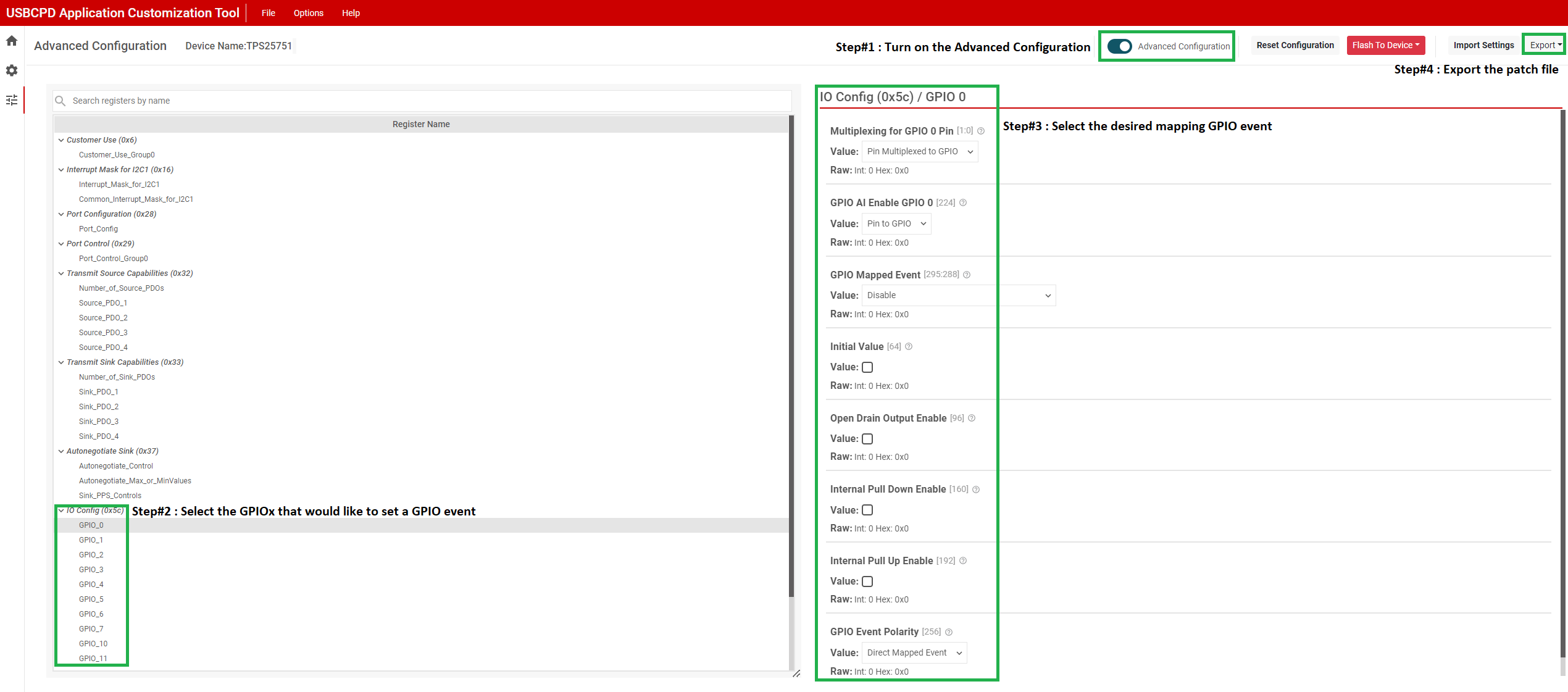
GPIOx can be configured as input type and output type with corresponding mapped event. USBCPB Application Customization Tool can easily generate the customized GPIOx setting in low region binary file. For example, if GPIOx needs to configure GPIO0 as output type with plugevent_port1 and initial value is 0. When the event occurring, GPIO0 report the 1. After finishing the setup and export the low region binary and issue the file when PTCH mode to APP mode transition.
 Figure 7-1 GPIOx Setup Using USBPCB
Application Customization Tool
Figure 7-1 GPIOx Setup Using USBPCB
Application Customization ToolFor GPIOx type, currently, these values are fixed by interrupt event and cannot be changed the type which means that TPS25751 does not allow use for general GPIOs to be input or output and read the status. Instead, based on which GPIO event you configure, the PD can automatically change the GPIO settings of the pin to be input or output.