SLVAFW1 August 2024 DRV8818
2.1 Experiment and Results
A set up was created in the lab using a DRV8818EVM and a function generator. The block diagram is shown in Figure 2-1. The function generator is used to provide a periodic voltage signal to the VREF pin with different duty cycles. The diodes prevent reverse current flow into the MCU from the function generator.
 Figure 2-1 Block Diagram of Manual VREF
Reduction Method
Figure 2-1 Block Diagram of Manual VREF
Reduction Method| Parameter | Value |
|---|---|
| VM | 24V |
| Mode | Mixed Decay |
| Speed | 1000 pps |
| Run time | 5 mins |
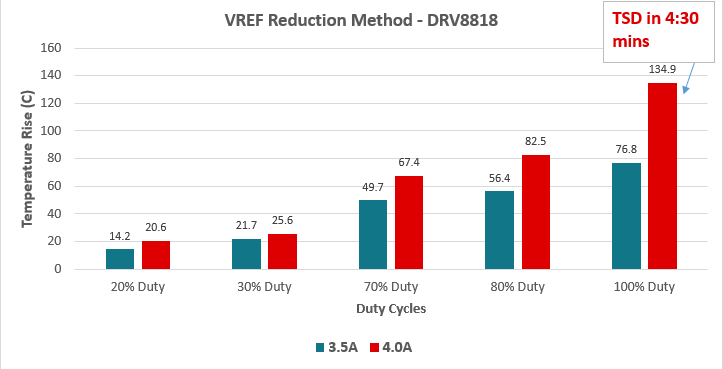
 Figure 2-2 Temperature Rise While PWM-ing
VREF
Figure 2-2 Temperature Rise While PWM-ing
VREFThus, the manual VREF reduction method reduces power consumption and improves thermals. Furthermore, this method also allows an increased value of motor peak regulated current without hitting the thermal shutdown (TSD) temperature value.
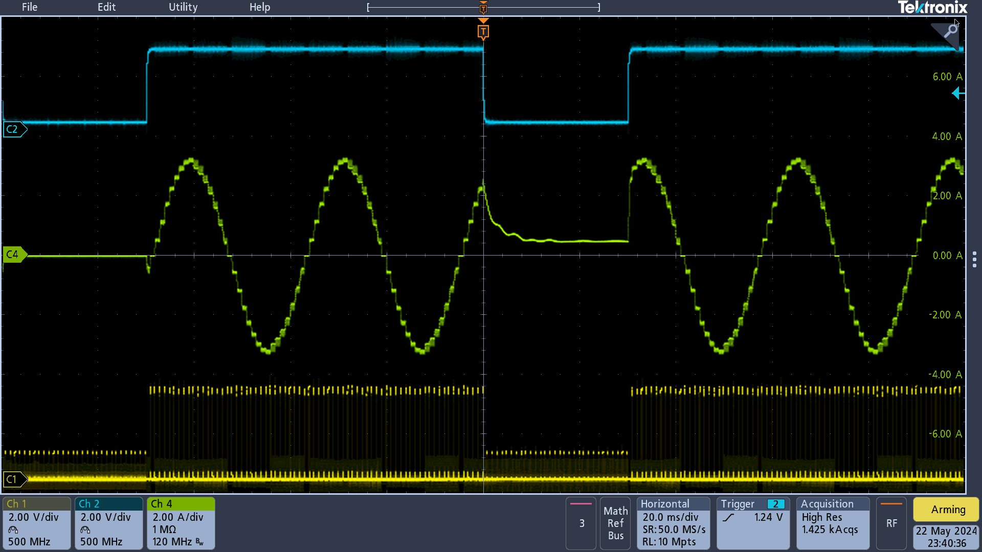
An example waveform is shown in Figure 2-3 where the blue signal denotes the periodic VREF voltage, green signal denotes the motor current, and yellow signal denotes the step signals.
 Figure 2-3 Example Waveform