SLVK086A january 2022 – may 2023 TPS7H4003-SEP
PRODUCTION DATA
- 1
- Single-Event Effects Test Report of the TPS7H4003-SEP Synchronous Step-Down Converter
- Trademarks
- 1 Introduction
- 2 Single-Event Effects (SEE)
- 3 Device and Test Board Information
- 4 Irradiation Facility and Setup
- 5 Depth, Range, and LETEFF Calculation
- 6 Test Setup and Procedures
- 7 Destructive Single-Event Effects (DSEE)
- 8 Single-Event Transients (SET)
- 9 Event Rate Calculations
- 10Summary
- A Appendix: Total Ionizing Dose From SEE Experiments
- B Appendix: References
- C Revision History
7.2 Single-Event Burnout (SEB) and Single-Event Gate Rupture (SEGR) Results
During the SEB/SEGR characterization, the device was tested at room temperature ≈25°C. The die temperature was monitored during the testing using a T-Type thermocouple attached to the thermal pad vias (on the bottom side of the EVM) with thermal paste. The thermocouple was hold on place by using high temperature tape (kapton-tape). Die-to-thermocouple temperature was verified using a IR-camera.
The species used for the SEB/SEGR testing was a Silver (109Ag) ion with an angle-of-incidence of 0° for an LETEFF = 48.2 MeV·cm2/mg (for more details refer to Section 5). The kinetic energy in the vacuum for this ion is 1.634 GeV (15-MeV/amu line). Flux of approximately 105 ions/cm2·s and a fluence of approximately 107 ions/cm2 were used for the six runs. Run duration to achieve this fluence was approximately 2 minutes. The three devices were powered up using the recommended maximum voltage of 7 V and the maximum load of 18 A. The TPS7H4003-SEP was tested under enabled and disabled modes, the device was disabled by using the TP2 and forcing EN to 5 V or 0 V, respectively, through channel one of an E36311A power supply. The Chroma Load was connected, even when the device was disabled, to help differentiate if a SET momentarily activated the device under the heavy-ion irradiation. During SEB/SEGR testing with the device disabled, no VOUT transient or input current events were observed. No SEB/SEGR events were observed during all six runs, indicating that the TPS7H4003-SEP is SEB/SEGR-free up to LETEFF = 48.7MeV·cm2/mg and across the full electrical specifications.Table 8-3 shows the SEB/SEGR test conditions and results. Figure 7-2 shows a plot of the current vs time for run # 6 (Enabled) and Figure 7-3 for run # 7 (Disabled).
| RUN # | UNIT # | ION | LETEFF (MeV·cm2/mg) | FLUX (ions·cm2/mg) | FLUENCE (# ions) | VIN (V) | ENABLED STATUS |
|---|---|---|---|---|---|---|---|
6 | 1 | 109Ag | 48.2 | 1.17 × 10⁵ | 1 × 10⁷ | 7 | Enabled |
7 | 1 | 109Ag | 48.2 | 1.15 × 10⁵ | 9.98 × 10⁶ | 7 | Disabled |
8 | 2 | 109Ag | 48.2 | 1.07 × 10⁴ | 1 × 10⁷ | 7 | Enabled |
9 | 2 | 109Ag | 48.2 | 1.07 × 10⁵ | 1 × 10⁷ | 7 | Disabled |
10 | 3 | 109Ag | 48.2 | 1.16 × 10⁵ | 1 × 10⁷ | 7 | Enabled |
11 | 3 | 109Ag | 48.2 | 1.45 × 10⁵ | 9.97 × 10⁶ | 7 | Disabled |
Using the MFTF method described in Single-Event Effects (SEE) Confidence Interval Calculations application report and combining (or summing) the fluences of the six runs @ 25°C (6.00 × 10⁷), the upper-bound cross-section (using a 95% confidence level) is calculated as:
σSEL ≤ 6.15 × 10⁻⁸ cm2/device for LETEFF = 48.2 MeV·cm2/mg and T = 25°C.
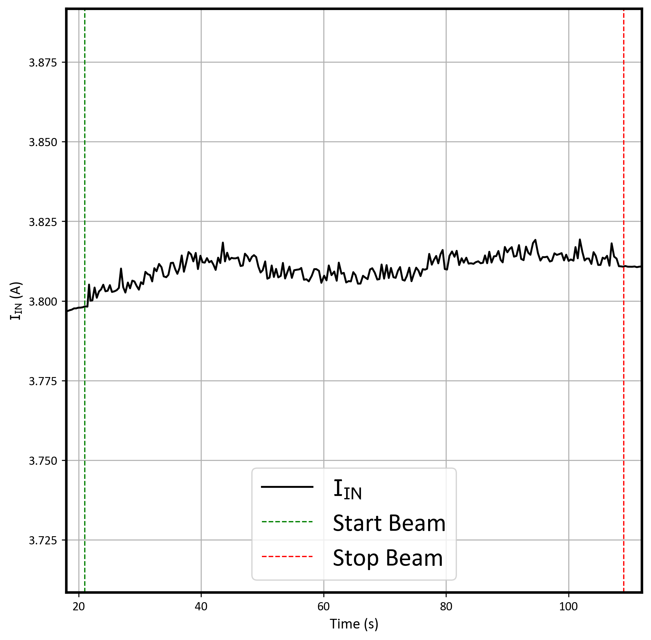 Figure 7-2 Current vs Time for Run # 6 (Enabled) for the TPS7H4003-SEP at T = 25°C
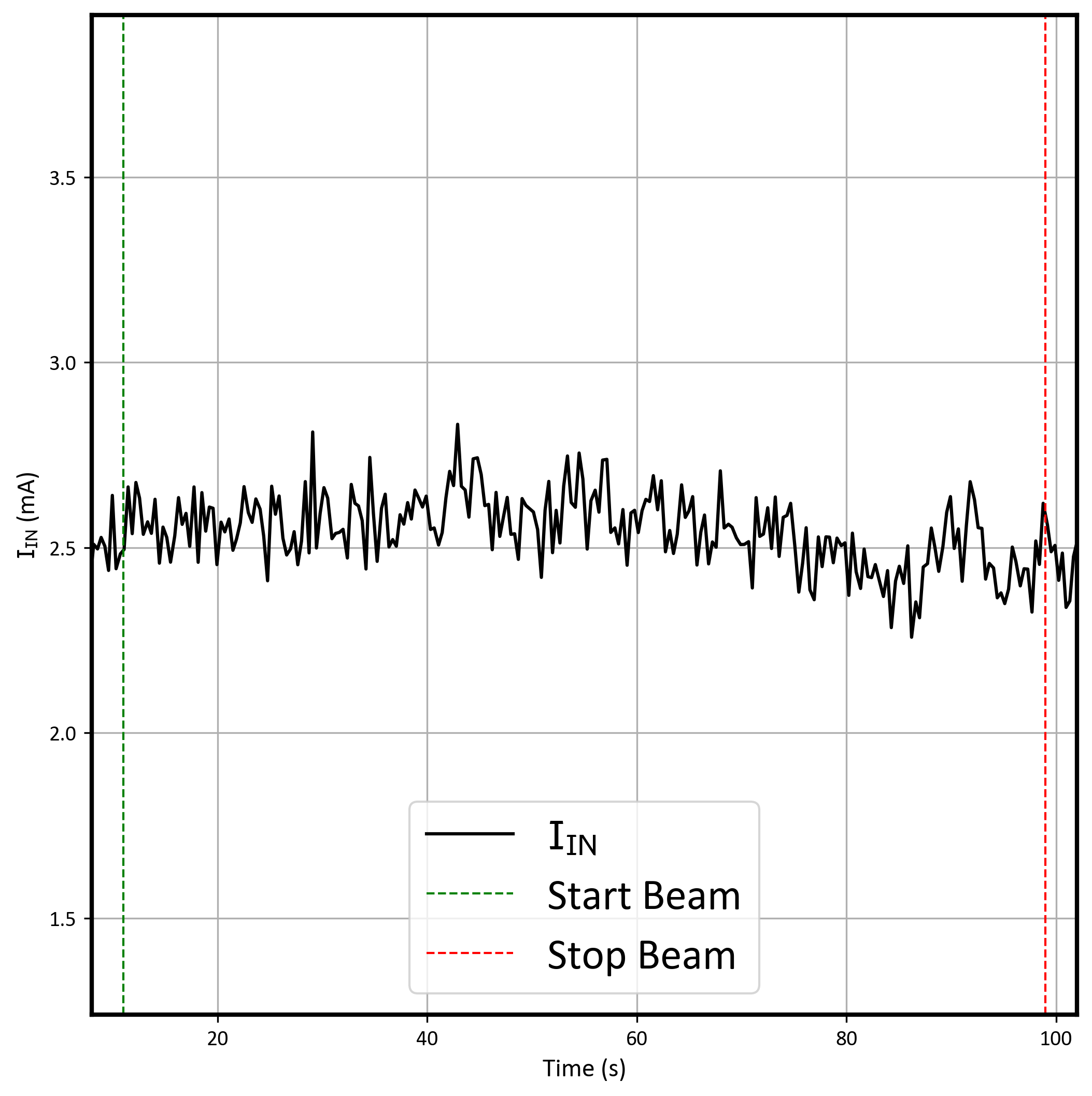 Figure 7-3 Current vs Time for Run # 7 (Disabled) for the TPS7H4003-SEP at T = 25°C
During the SEB On runs, there were recorded transients on VOUT that were not seen during SET testing (i.e. Only at "worst case" VIN voltages of 7-V). The following histograms and transient plot show the VOUT transient information seen only during destructive testing.
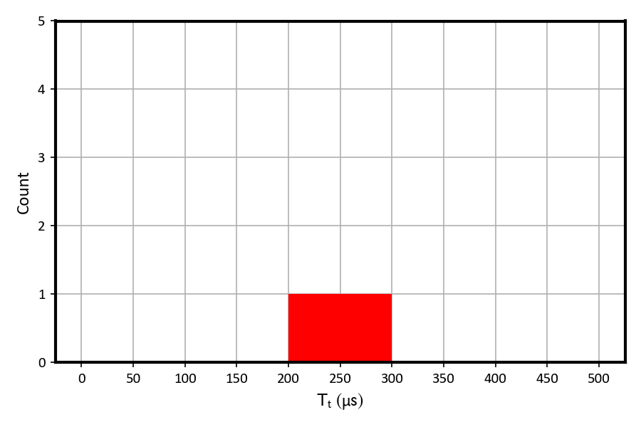 Figure 7-4 Histogram of the Transient Time for VOUT SETs on Run # 6
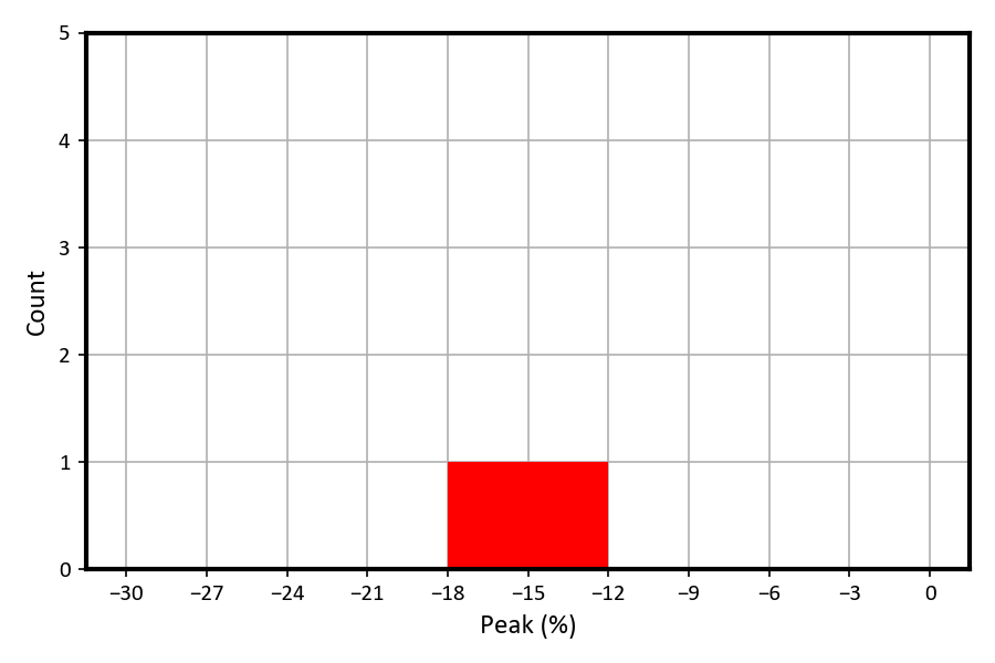 Figure 7-5 Histogram of the Normalized Amplitude for the Positive and Negative VOUT SETs on Run # 6
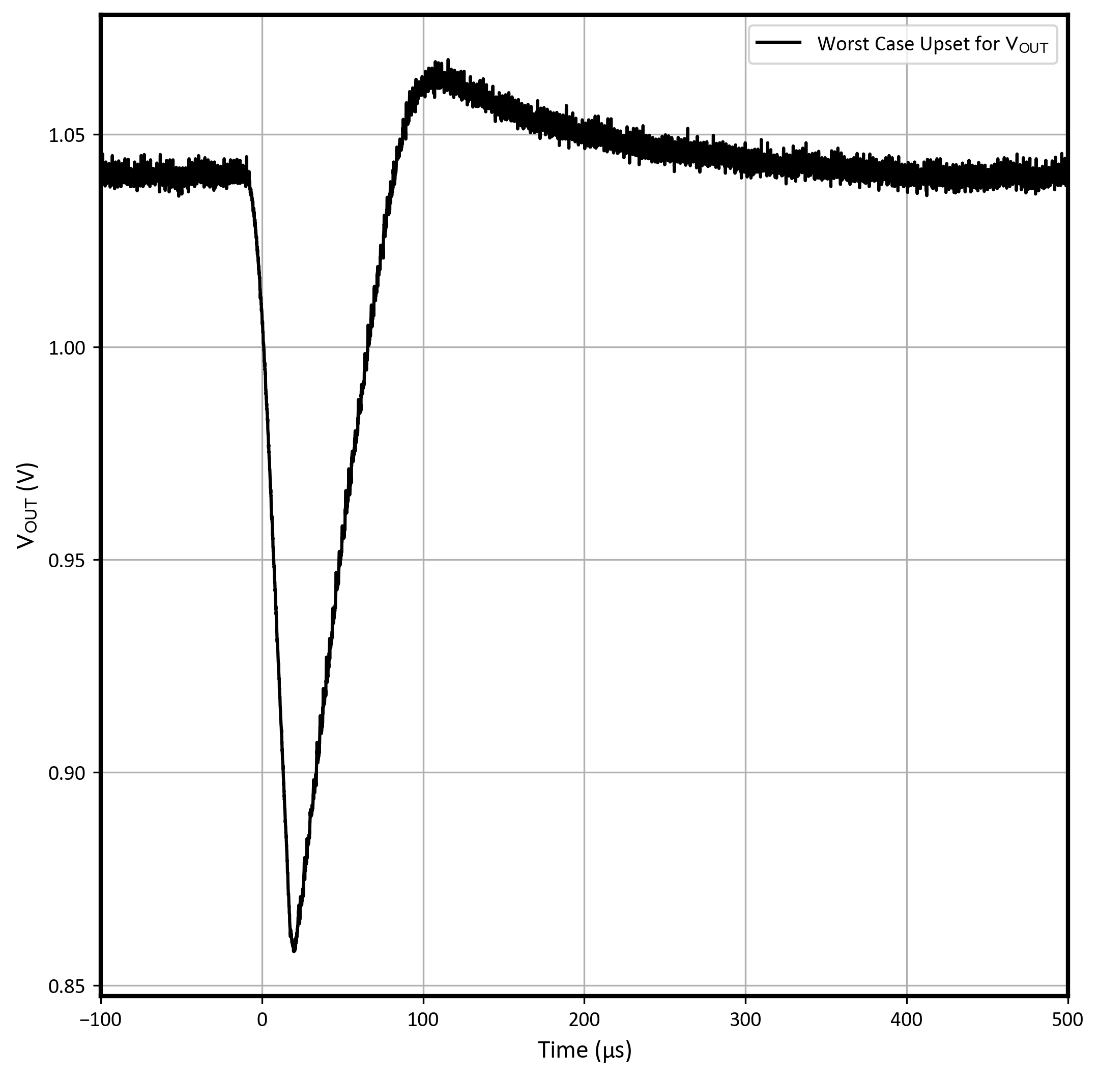 Figure 7-6 Worst Case Positive and Negative Polarity VOUTSET for Run # 6