-
TPS7A4501-SP Low-Dropout Voltage Regulator
- 1 Features
- 2 Applications
- 3 Description
- 4 Revision History
- 5 Description (continued)
- 6 Pin Configuration and Functions
- 7 Specifications
- 8 Detailed Description
- 9 Application and Implementation
- 10Power Supply Recommendations
- 11Layout
- 12Device and Documentation Support
- 13Mechanical, Packaging, and Orderable Information
- IMPORTANT NOTICE
TPS7A4501-SP Low-Dropout Voltage Regulator
1 Features
- QMLV Qualified SMD 5962-12224
- Adjustable Output from 1.21 to 20 V
- Optimized for Fast-Transient Response
- High Output Voltage Accuracy: 1.15% at 25°C (Typical)
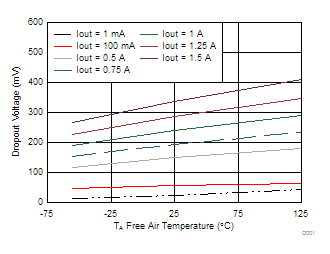
- Dropout Voltage: 200 mV With ILOAD = 750 mA (Typical)
- Low Noise: 50 μVRMS (10 Hz to 100 kHz) for VOUT = 5 V
- High Ripple Rejection: 68 dB at 1 kHz
- 1-mA Quiescent Current
- No Protection Diodes Needed
- Stable With Ceramic Output Capacitor
- Reverse-Battery Protection
- Reverse Current Protection
- 5962-1222402VHA:
- Wide Vin 2.3 to 20 V
- Output Current: 750 mA
- 5962R1222403VXC:
- Wide Vin 2.9 to 20 V
- Output Current: 1.5 A
- Thermally-Enhanced HKU Package
- Radiation Hardness Assurance (RHA) up to Total Ionizing Dose (TID) 100 krad (Si)
- Exhibits Low Dose Rate Sensitivity But Remains Within the Pre-Radiation Electrical Limits at 100 krad Total Dose Level, as Allowed by MIL-STD-883, TM1019
2 Applications
- RF Components VCOs, Receivers, ADCs, Amplifiers and Clock Distributions
- Clean Analog Supply Requirements
- Available in Military (–55°C to 125°C) Temperature Range
- Engineering Evaluation (/EM) Samples are Available (1)
3 Description
The TPS7A4501-SP is a low-dropout (LDO) regulator optimized for fast-transient response. The 5962-1222402VHA can supply 750 mA of output current with a dropout voltage of 300 mV. The 5962R1222403VXC can supply 1.5 A of output current with a dropout voltage of 320 mV. Quiescent current is well controlled; it does not rise in dropout, as with many other regulators. In addition to fast transient response, the TPS7A4501-SP regulator has very-low output noise, which makes it ideal for sensitive RF supply applications.
Device Information(1)
| PART NUMBER | PACKAGE | BODY SIZE (NOM) |
|---|---|---|
| TPS7A4501-SP | CFP [U] (10) | 6.35 mm × 6.35 mm |
| CFP [HKU] (10) | 7.02 mm × 6.86 mm | |
| KGD | N/A(2) |
- For all available packages, see the orderable addendum at the end of the data sheet.
- Bare die in waffle pack
SPACE
Dropout Voltage vs Temperature

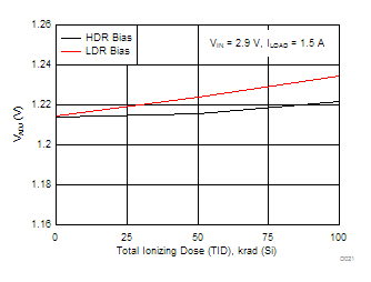
VADJ Radiation Drift Curve

4 Revision History
Changes from C Revision (October 2014) to D Revision
- Replaced the Dissipation Ratings table with the Thermal Information tableGo
- Added 5962-1222402V9A to Electrical Characteristics (5962-1222402VHA and 5962-1222402V9A)Go
- Added new part 5962R1222403V9A to Electrical Characteristics (5962R1222403VXC and 5962R1222403V9A)Go
Changes from B Revision (October 2014) to C Revision
- Removed VDO, dropout voltage with test condition VOUT = 2.4 VGo
- Added thermal shutdown temperature Go
- Added thermal shutdown temperature Go
- Added thermal shutdown information to Protection FeaturesGo
Changes from A Revision (January 2014) to B Revision
- Added limits for the new device type, 5962R1222Go
- Added Handling Ratings table, Feature Description section, Device Functional Modes, Application and Implementation section, Power Supply Recommendations section, Layout section, Device and Documentation Support section, and Mechanical, Packaging, and Orderable Information section Go
- Added thermal information for the HKU package Go
Changes from * Revision (December 2013) to A Revision
- Changed Product Status from Product Preview to Production DataGo
5 Description (continued)
Output voltage range is from 1.21 to 20 V. The TPS7A4501-SP is stable with output capacitance as low as 10 μF. Small ceramic capacitors can be used without the necessary addition of ESR, as is common with other regulators. Internal protection circuitry includes reverse-battery protection, current limiting, thermal limiting, and reverse-current protection. The device is available as an adjustable device with a 1.21-V reference voltage. The 5962-1222402VHA is available in 10-pin CFP (U) package and 5962R1222403VXC is available in thermally-enhanced 10-pin CFP (HKU) package. Known good die (KGD) option is available for both 5962-1222402V9A for non-RHA version and 5962R1222403V9A for RHA.
6 Pin Configuration and Functions


Pin Functions
| PIN | I/O | DESCRIPTION | |
|---|---|---|---|
| NAME | NO. | ||
| SHDN | 1 | I | Shutdown. SHDN is used to put the TPS7A4501 regulator into a low-power shutdown state. The output is off when SHDN is pulled low. SHDN can be driven by 5-V logic, 3-V logic, or open-collector logic with a pullup resistor. The pullup resistor is required to supply the pullup current of the open-collector gate, normally several microamperes, and SHDN current, typically 3 μA. If unused, the user must connect SHDN to VIN. The device is in the low-power shutdown state if SHDN is not connected. |
| IN | 2 | I | Input. Power is supplied to the device through IN. A bypass capacitor is required on this pin if the device is more than six inches away from the main input filter capacitor. In general, the output impedance of a battery rises with frequency, so it is advisable to include a bypass capacitor in battery-powered circuits. A bypass capacitor (ceramic) in the range of 1 to 10 μF is sufficient. The TPS7A4501 regulator is designed to withstand reverse voltages on IN with respect to ground and on OUT. In the case of a reverse input, which can happen if a battery is plugged in backwards, the device functions as if there is a diode in series with its input. No reverse current flows into the regulator, and no reverse voltage appears at the load. The device protects both itself and the load. |
| 3 | |||
| 4 | |||
| NC | 5 | NC | This pin is not connected to any internal circuitry. It can be left floating or tied to VIN or GND. |
| OUT | 6 | O | Output. The output supplies power to the load. To prevent oscillations, use a minimum output capacitor (ceramic) of 10 μF. Applications with large transient loads to limit peak voltage transients require larger output capacitors. |
| 7 | |||
| 8 | |||
| ADJ | 9 | I | Adjust. This is the input to the error amplifier. ADJ is internally clamped to ±7 V. It has a bias current of 3 μA that flows into the pin. ADJ voltage is 1.21 V referenced to ground, and the output voltage range is 1.21 to 20 V. |
| GND | 10 | — | Ground |
| Thermal Vias(1) | — | — | The exposed thermal vias of the HKU package should be connected to a wide ground plane for effective heat dissipation. Refer to Figure 30 and Figure 31 for the typical footprint of the HKU package. |
Bare Die Information
| DIE THICKNESS | BACKSIDE FINISH | BACKSIDE POTENTIAL | BOND PAD METALLIZATION COMPOSITION |
BOND PAD THICKNESS |
|---|---|---|---|---|
| 15 mils | Silicon with backgrind | Floating | TiW/AlCu2 | 1627 nm |

Bond Pad Coordinates in Microns(1)
| DESCRIPTION | PAD NUMBER | X MIN | Y MIN | X MAX | Y MAX |
|---|---|---|---|---|---|
| SHDN | 1 | 1729.25 | 55.5 | 1879.25 | 205.5 |
| IN | 2 | 1037.25 | 875 | 1187.25 | 1025 |
| IN | 3 | 1460.75 | 1255.5 | 1610.75 | 1405.5 |
| IN | 4 | 1037.75 | 1384.5 | 1187.75 | 1534.5 |
| OUT | 5 | 774.25 | 1634.75 | 924.25 | 1784.75 |
| OUT | 6 | 675.25 | 1166 | 825.25 | 1316 |
| OUT | 7 | 345.5 | 1299.25 | 495.5 | 1449.25 |
| SENSE/ADJ | 8 | 55.5 | 213 | 205.5 | 363 |
| GND | 9 | 244 | 17.5 | 394 | 167.5 |