SLVSDM4D November 2018 – December 2019 TPS1HA08-Q1
PRODUCTION DATA.
- 1 Features
- 2 Applications
- 3 Description
- 4 Revision History
- 5 Device Comparison Table
- 6 Pin Configuration and Functions
- 7 Specifications
- 8 Parameter Measurement Information
-
9 Detailed Description
- 9.1 Overview
- 9.2 Functional Block Diagram
- 9.3
Feature Description
- 9.3.1 Protection Mechanisms
- 9.3.2 Diagnostic Mechanisms
- 9.3.3 Enable Watchdog
- 9.4 Device Functional Modes
- 10Application and Implementation
- 11Power Supply Recommendations
- 12Layout
- 13Device and Documentation Support
- 14Mechanical, Packaging, and Orderable Information
9.3.1.4.2 Driving Inductive and Capacitive Loads
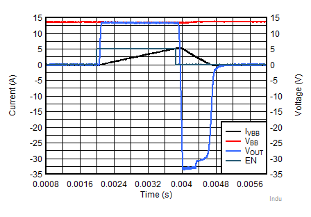
When switching off an inductive load, the inductor may impose a negative voltage on the output of the switch. The includes a voltage clamp to limit voltage across the FET. The maximum acceptable load inductance is a function of the device robustness. With a 5 mH load, the can withstand a single pulse of 95 mJ inductive dissipation at 125°C and can withstand 56 mJ of inductive dissipation with a 10 Hz repetitive pulse. If the application parameters exceed this device limit, it is necessary to use a protection device like a freewheeling diode to dissipate the energy stored in the inductor. Figure 40 shows the discharging a 5 mH load that is driven at 5 A.
 Figure 40. Inductive Discharge (5 mH, 5 A)
 In addition, the current limit provides an ideal way to charge a capacitive load safely with limited inrush current. With no protection, charging a large capacitive load can lead to high inrush currents that pull a supply down, however by using the low current limit device options the capacitive load can be safely charged.
For more information on driving inductive or capacitive loads, reference TI's "How To Drive Inductive, Capacitive, and Lighting Loads with Smart High Side Switch application report.