SLVSDT3D January   2018  – December 2019 TPS25221

PRODUCTION DATA.  

  1. Features
  2. Applications
  3. Description
    1.     Device Images
      1.      Simplified Schematic
  4. Revision History
  5. Device Comparison Table
  6. Pin Configuration and Functions
    1.     Pin Functions
  7. Specifications
    1. 7.1 Absolute Maximum Ratings
    2. 7.2 ESD Ratings
    3. 7.3 Recommended Operating Conditions
    4. 7.4 Thermal Information
    5. 7.5 Electrical Characteristics
    6. 7.6 Typical Characteristics
  8. Parameter Measurement Information
  9. Detailed Description
    1. 9.1 Overview
    2. 9.2 Functional Block Diagram
    3. 9.3 Feature Description
      1. 9.3.1 Over-current Conditions
      2. 9.3.2 Fault Response
      3. 9.3.3 Undervoltage Lockout (UVLO)
      4. 9.3.4 Enable, (EN)
      5. 9.3.5 Thermal Sense
    4. 9.4 Device Functional Modes
    5. 9.5 Programming
      1. 9.5.1 Programming the Current-Limit Threshold
  10. 10Application and Implementation
    1. 10.1 Application Information
      1. 10.1.1 Constant-Current
    2. 10.2 Typical Applications
      1. 10.2.1 Two-Level Current-Limit Circuit
        1. 10.2.1.1 Design Requirements
        2. 10.2.1.2 Detailed Design Procedures
          1. 10.2.1.2.1 Designing Above a Minimum Current Limit
          2. 10.2.1.2.2 Designing Below a Maximum Current Limit
          3. 10.2.1.2.3 Accounting for Resistor Tolerance
          4. 10.2.1.2.4 Input and Output Capacitance
        3. 10.2.1.3 Application Curve
      2. 10.2.2 Auto-Retry Functionality
        1. 10.2.2.1 Design Requirements (added)
        2. 10.2.2.2 Detailed Design Procedure
      3. 10.2.3 Typical Application as USB Power Switch
        1. 10.2.3.1 Design Requirements
          1. 10.2.3.1.1 USB Power-Distribution Requirements
        2. 10.2.3.2 Detailed Design Procedure
          1. 10.2.3.2.1 Universal Serial Bus (USB) Power-Distribution Requirements
  11. 11Power Supply Recommendations
    1. 11.1 Self-Powered and Bus-Powered Hubs
    2. 11.2 Low-Power Bus-Powered and High-Power Bus-Powered Functions
    3. 11.3 Power Dissipation and Junction Temperature
  12. 12Layout
    1. 12.1 Layout Guidelines
    2. 12.2 Layout Example
  13. 13Device and Documentation Support
    1. 13.1 Device Support
      1. 13.1.1 Third-Party Products Disclaimer
    2. 13.2 Documentation Support
      1. 13.2.1 Related Documentation
    3. 13.3 Receiving Notification of Documentation Updates
    4. 13.4 Community Resources
    5. 13.5 Trademarks
    6. 13.6 Electrostatic Discharge Caution
    7. 13.7 Glossary
  14. 14Mechanical, Packaging, and Orderable Information

Auto-Retry Functionality

Some applications require that an over-current condition disables the part momentarily during a fault condition and re-enables after a pre-set time. This auto-retry functionality can be implemented with an external resistor and capacitor. During a fault condition, FAULT pulls low disabling the part. The part is disabled when EN is pulled low, and FAULT goes high impedance allowing CRETRY to begin charging. The part re-enables when the voltage on EN reaches the turn-on threshold, and the auto-retry time is determined by the resistor-capacitor time constant. The device continues to cycle in this manner until the fault condition is removed.
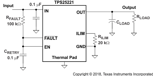
TPS25221 auto_func_slvsdt3.gifFigure 27. Auto-Retry Functionality

Some applications require auto-retry functionality and the ability to enable or disable with an external logic signal. Figure 28 shows how an external logic signal can drive EN through RFAULT and maintain auto-retry functionality. The resistor-capacitor time constant determines the auto-retry time-out period.
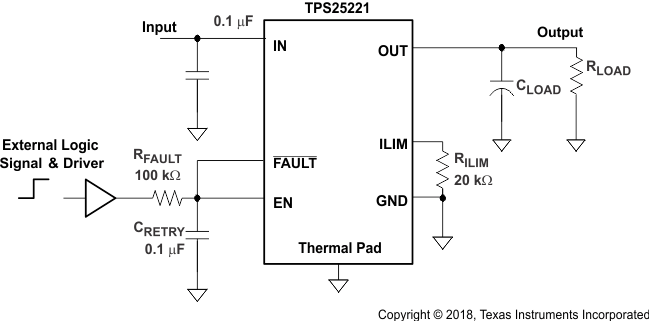
TPS25221 ext_en_sig_slvsdt3.gifFigure 28. Auto-Retry Functionality With External EN Signal