SLVU346A January   2010  – February 2022 TPS51218


  1.   Trademarks
  2. 1Description
    1. 1.1 Typical Applications
    2. 1.2 Features
  3. 2Electrical Performance Specifications
  4. 3Schematic
  5. 4Test Setup
    1. 4.1 Test Equipment
    2. 4.2 Recommended Test Setup
      1. 4.2.1 Configurations
      2. 4.2.2 Input Connections
      3. 4.2.3 Output Connections
      4. 4.2.4 Other Connections
  6. 5Test Procedure
    1. 5.1 Line/Load Regulation and Efficiency Measurement Procedure
    2. 5.2 List of Test Points
    3. 5.3 Equipment Shutdown
  7. 6Performance Data and Typical Characteristic Curves
    1. 6.1 Efficiency
    2. 6.2 Load Regulation
    3. 6.3 Transient Response
    4. 6.4 Output Ripple
    5. 6.5 Switch Node Voltage
    6. 6.6 Turn-On Waveform
    7. 6.7 Turn-Off Waveform
    8. 6.8 Output 1.1-V Prebias Turn-On
  8. 7EVM Assembly Drawing and PCB Layout
  9. 8Bill of Materials
  10. 9Revision History

EVM Assembly Drawing and PCB Layout

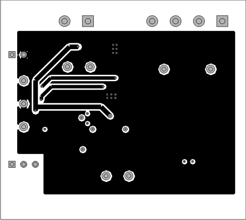
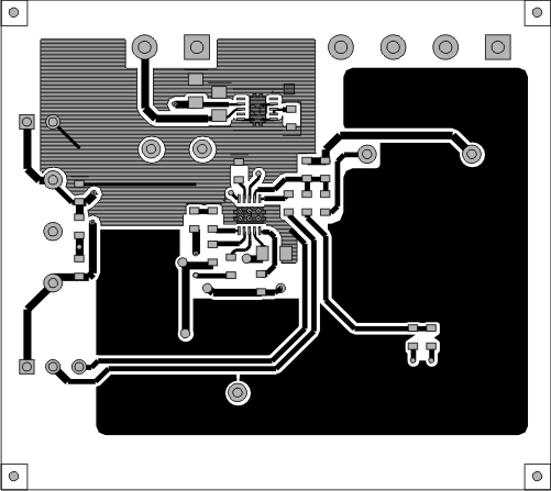
Figure 7-1 through Figure 7-6 show the design of the TPS51218EVM printed-circuit board. The EVM has been designed using a four-layer, 2-oz copper circuit board.
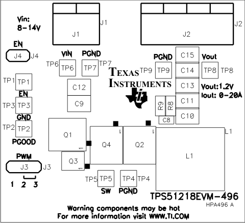
GUID-0E349D30-9DF2-48AF-BEF2-DA548C8AA4EA-low.gifFigure 7-1 TPS51218EVM Top Layer Assembly Drawing, Top View
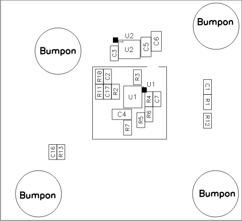
GUID-7FE8003B-777A-4E03-AD86-CA256505E673-low.gifFigure 7-2 TPS51218EVM Bottom Assembly Drawing, Bottom View
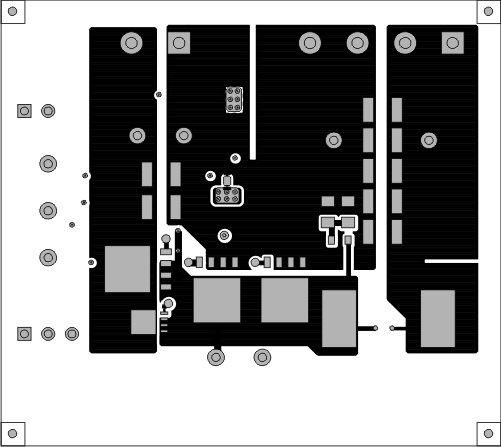
GUID-B3A1E2B2-0381-46DF-B8D3-1C0E52848EC0-low.gifFigure 7-3 TPS51218EVM Top Copper, Top View
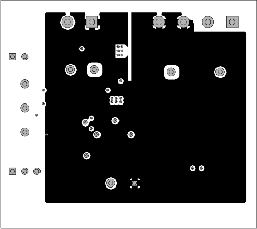
GUID-FBC832C3-D663-4307-88DC-474E443EBE6B-low.gifFigure 7-4 TPS51218EVM Internal Layer 1
GUID-D25B40C6-143F-4024-BC34-589E60D977D8-low.gifFigure 7-5 TPS51218EVM Internal Layer 2
GUID-FD012816-524D-48B9-9760-5F261A1D1124-low.gifFigure 7-6 TPS51218EVM Bottom Layer