SLVUA33A March 2014 – July 2021 TPS563900
1.3.1 Output Voltage Setpoint
The output voltage of the EVM is set either externally using a voltage divider or internally using the integrated I2C interface. The external adjustment of the output voltage for VOUT1 is set by the resistor divider network of R10 and R11. The external adjustment of the output voltage for VOUT2 is set by the resistor divider network of R16 and R17. R10 and R16 are fixed at 40.2 kΩ. To change the output voltage of VOUT1 or VOUT2, it is necessary to change the value of resistor R11 or R17. Changing the value of R11 or R17 can change the output voltage in the range of 0.68 V to 1.95 V. The value of R11 or R17 for a specific output voltage can be calculated using Equation 1 or Equation 2.
Equation 1.  | or | Equation 2.  |
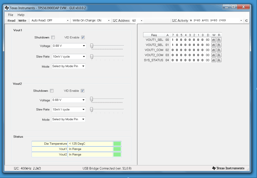
The output voltage can also be set using the optional VID control using the I2C interface. The EVM is designed so that the J2 connector is compatible with the HPA172 USB Interface Adapter. Using that control and TPS563900 GUI_ver_0_0_0_2 software allows the output voltage to be programmed to any of 128 preset voltages from 0.68 V to 1.95 V. JP2-2 and JP2-3 should be covered to select the default address. JP3 should be open to allow the I2C pull up to be supplied from the USB adapter, available from www.ti.com/tool/usb-to-gpio. The USB adapter is also available from the TI eStore. See the TPS563900 datasheet (SLVSCC7) for a complete description of the available codes. With the software running and the cable attached, run the GUI interface software (SLVC558). Figure 1-1 shows the GUI interface.
 Figure 1-1 TPS563900 GUI_ver_0_0_0_2 Screen
To change the output voltages, ensure that the VID Enable check boxes are checked. The voltages can be interactively changed using the slide controls when "Write On Change: ON" is active. See the TPS563900 datasheet for further details.