SLVUAC4A October 2014 – May 2021 TPS65400
4.1 Headers Description and Jumper Placement
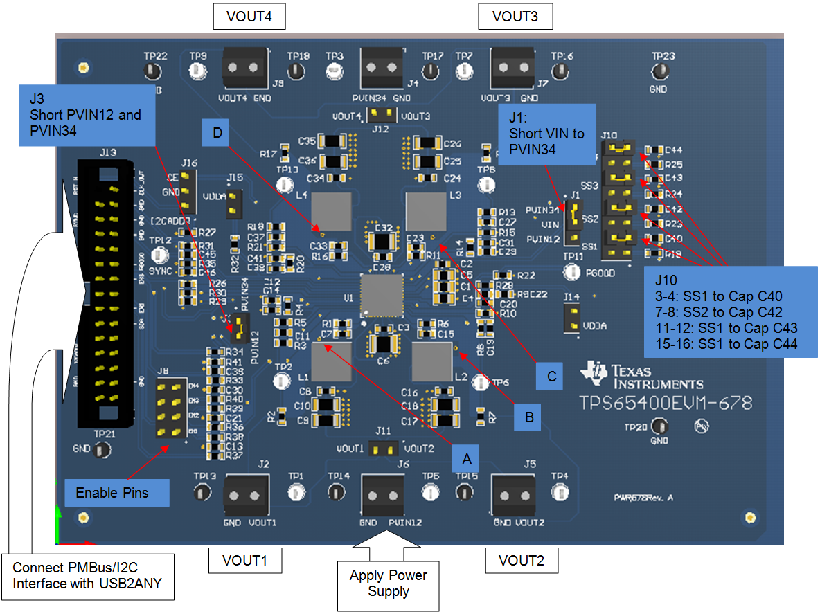
Figure 4-1 illustrates the header descriptions and jumper placement on the EVM.
 Figure 4-1 Headers Description and Jumper Placement
Test points:
- LX of VOUT1
- LX of VOUT2
- LX of VOUT3
- LX of VOUT4
VOUT1, VOUT2, VOUT3, VOUT4
Table 4-1 Input/Output Connection
| No. | Function | Description |
|---|---|---|
| J2 | Buck1 Connector | Output of Buck1 |
| J5 | Buck2 Connector | Output of Buck2 |
| J7 | Buck3 Connector | Output of Buck3 |
| J9 | Buck4 Connector | Output of Buck4 |
| J6 | Buck1/2/3/4 VIN Connector | Apply power supply to this connector |
| J13 | PMBus/I2C Interface connector | Communication via PMBus/I2C Interface |
Table 4-2 Jumpers
| No. | Functions | Description |
|---|---|---|
| JP1-PVIN34-Vin-PVIN12 | Short VIN to PVIN34 | Vin tied to PVIN34 |
| JP3-PVIN12-PVIN34 | Short PVIN12 with PVIN34 | PVIN34 tied to PVIN12 |
| JP10-3-4 | Connect Cap to SS1 | tied SS1 to C40 |
| JP10-7-8 | Connect Cap to SS2 | tied SS2 to C42 |
| JP10-11-12 | Connect Cap to SS3 | tied SS3 to C43 |
| JP10-15-16 | Connect Cap to SS4 | tied SS4 to C44 |