SLVUAC4A October 2014 – May 2021 TPS65400
4.3 Hardware Setup
After connecting the power supply to J6 and turning on the power supply, the EVM regulates the output voltages to the value listed in Table 1-1. Additional input capacitance may be required in order to mitigate the inductive voltage droop that may occur during a load transient event.
In order to change the output voltage by sending the digital control signal via a PC running the TPS65400 controller software and USB2ANY interface box, perform the following steps:
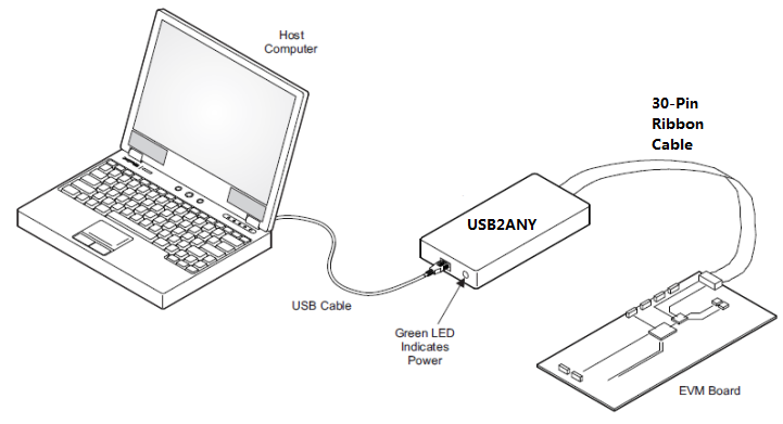
- Connect the USB port of USB2ANY to the PC using the USB cable and the other end to J13 of the TPS65400 using the supplied 30-pin ribbon cable (Figure 4-2). The connectors on the ribbon cable are keyed to prevent incorrect installation.
- Connect the power supply on J6 and turn on the power supply.
- Run the software as explained in Section 4.4.
 Figure 4-2 USB Interface Adapter Quick Connection Diagram