SLVUAI7B August   2016  – June 2021 TPS62135 , TPS62136


  1.   Trademarks
  2. 1Introduction
    1. 1.1 Performance Specification
    2. 1.2 Modifications
      1. 1.2.1 Input and Output Capacitors
      2. 1.2.2 Soft-Start Time
      3. 1.2.3 Configurable Tracking Voltage
      4. 1.2.4 Configurable Enable Threshold Voltage
      5. 1.2.5 Loop Response Measurement
  3. 2Setup
    1. 2.1 Connector Descriptions
    2. 2.2 Hardware Setup
  4. 3TPS6213xEVM-698 Test Results
  5. 4Board Layout
  6. 5Schematic and Bill of Materials
    1. 5.1 Schematic
    2. 5.2 Bill of Materials
  7. 6Revision History

Board Layout

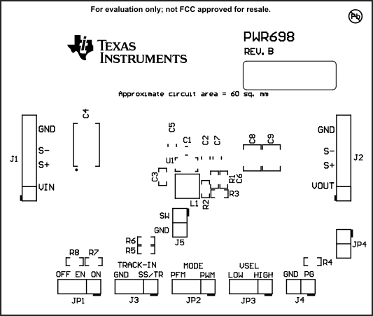
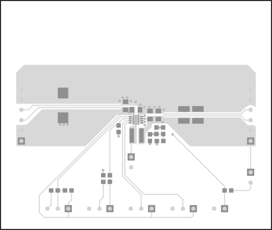
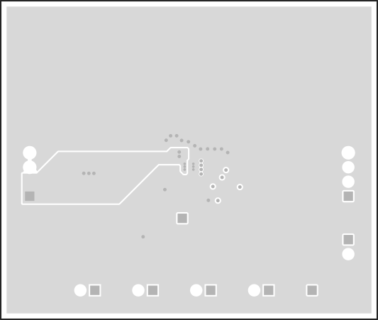
This section provides the TPS6213xEVM-698 board layout and illustrations. The Gerbers are available on the EVM product pages: TPS62135EVM-698 and TPS62136EVM-698.
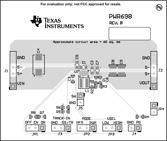
GUID-7A77B97A-2051-4553-B732-F0E4160D575E-low.gifFigure 4-1 Top Assembly
GUID-FC8E6708-7258-4945-8508-2D9144B8CD3C-low.gifFigure 4-2 Top Overlay
GUID-54F407AB-9F26-4126-A0FC-D8B0949798E8-low.gifFigure 4-3 Top Layer
GUID-7BA8C0AA-16D6-48E4-9480-0A819F8E6C4F-low.gifFigure 4-4 Internal Layer 1
GUID-278FEFEA-1AFC-4CE1-AC25-9318AB6F039E-low.gifFigure 4-5 Internal Layer 2
GUID-ED19938A-5086-45E5-9501-6D0EF82DEF97-low.gifFigure 4-6 Bottom Layer