SLVUAK9A December 2015 – May 2021 TPS65265
2 Schematic
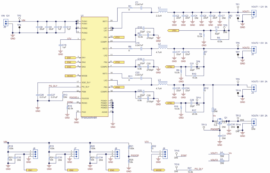
Figure 2-1 illustrates the TPS65265EVM-705 EVM schematic.
 Figure 2-1 TPS65265EVM-705 Schematic
SLVUAK9A December 2015 – May 2021 TPS65265
Figure 2-1 illustrates the TPS65265EVM-705 EVM schematic.
 Figure 2-1 TPS65265EVM-705 Schematic