SLVUBB4B November 2017 – February 2023
- Abstract
- Trademarks
- 1 Topologies Window
- 2 FET Losses Calculator
- 3 Load Step Calculator
- 4 Capacitor Current Sharing Calculator
- 5 AC/DC Bulk Capacitor Calculator
- 6 RCD-Snubber Calculator for Flyback Converters
- 7 RC-Snubber Calculator
- 8 Output Voltage Resistor Divider
- 9 Dynamic Analog Output Voltage Scaling
- 10Dynamic Digital Output Voltage Scaling
- 11Unit Converter
-
12Loop Calculator
- 12.1 Inputs
- 12.2
Transfer Functions
- 12.2.1 Output Impedance Transfer Function
- 12.2.2 Transfer Function VMC Buck Power Stage
- 12.2.3 Transfer Function CMC Buck Power Stage
- 12.2.4 Transfer Function CMC Boost Power Stage
- 12.2.5 Transfer Function CMC Inverting Buck-Boost Power Stage
- 12.2.6 Transfer Function CMC Forward Power Stage
- 12.2.7 Transfer Function CMC Flyback Power Stage
- 12.2.8 Transfer Function Closed Loop
- 12.2.9 Transfer Function Isolated Type II Compensation Network With a Zener Clamp
- 12.2.10 Transfer Function Isolated Type II Compensation Network Without a Zener Clamp
- 13Filter Designer
- 14Additional Information
- 15Revision History
4 Capacitor Current Sharing Calculator
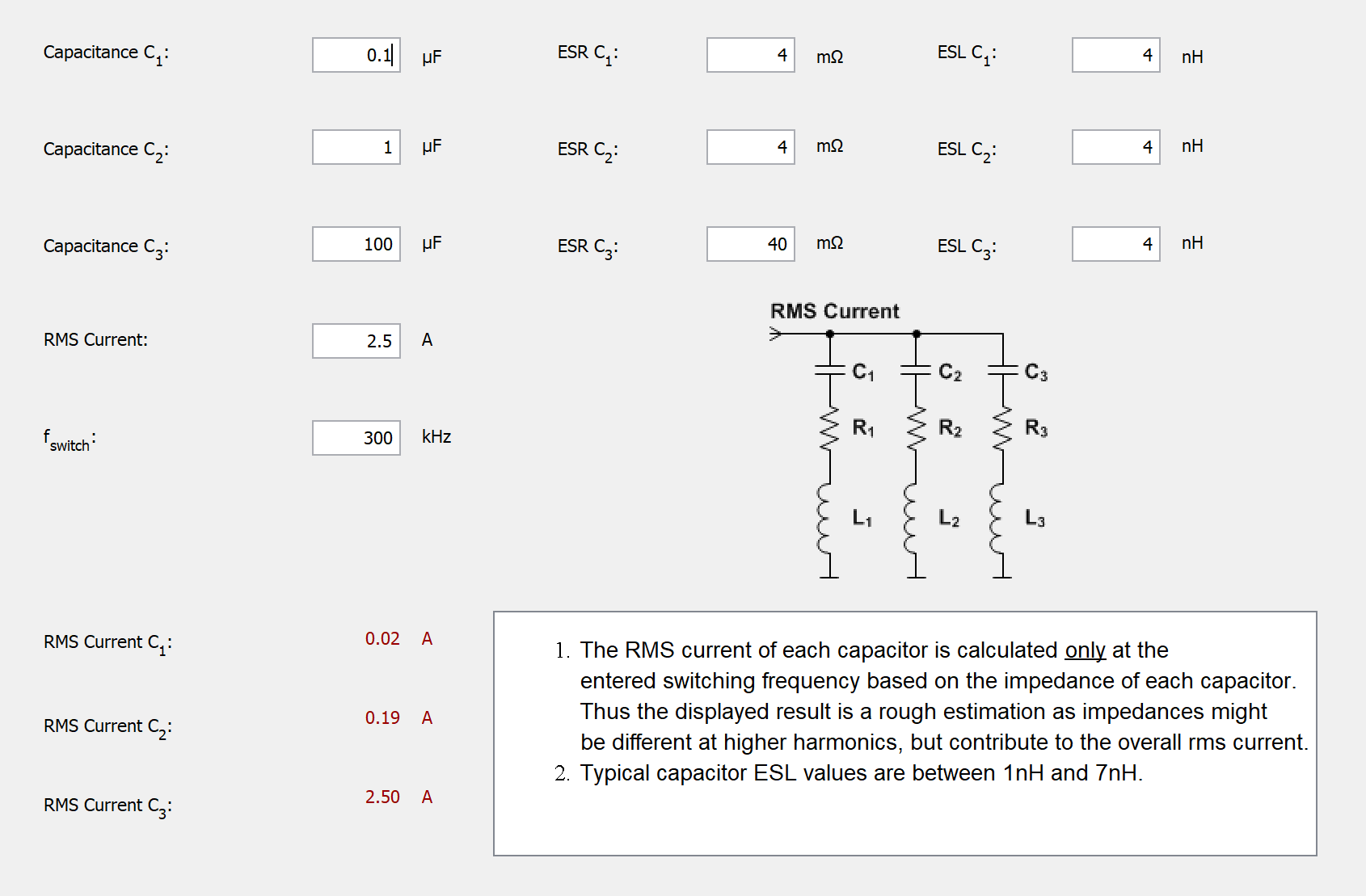
When connecting different kinds of capacitors in parallel at the input or output of a power supply, the RMS current going through each capacitor is different as it depends on the impedance of the capacitors across the entire frequency range. For exact results for the RMS current per capacitor, impedances and currents must be calculated for all harmonics of the switching frequency. The RMS current for each harmonic must be derived with a Fast Fourier Transformation (FFT) of the total current signal based on the ratio between total impedance and single-capacitor impedance at that harmonic frequency.
#SLVUBB48326 shows the Capacitor Current Sharing Calculator.
In Power Stage Designer, the impedances and the RMS currents are only calculated at the switching frequency. Thus, the resulting RMS currents are rough estimations.
 Figure 4-1 Capacitor
Current Sharing Calculator
Figure 4-1 Capacitor
Current Sharing CalculatorThe impedance for one capacitor at the switching frequency (n can be 1, 2, or 3 and refers to the capacitor index) can be calculated as indicated in #GUID-52184369-1A68-4F95-8C95-7C0EC84E18A8:
Typical ESL values for capacitors are from 1 nH to 7 nH. By assuming 6 nH/cm as parasitic inductance for a conductor, the inductance for a ceramic capacitor can be estimated by multiplying this value with the capacitor length. PCB traces and vias can increase this value slightly (see [1]).
The total impedance of three parallel capacitors at the switching frequency results as seen in #SLVUBB47688:
The RMS current of one capacitor, while neglecting all other harmonics besides the switching frequency, can be calculated as seen in #GUID-B13DFF4F-7176-4C44-82B3-972C5196E89E: