SLVUBX8B October 2020 – December 2021 TPS2661
- Trademarks
- 1Introduction
- 2Description
- 3Schematic
- 4General Configurations
-
5Test Setup and Procedures
- 5.1 Overload Protection Test
- 5.2 Output Short-Circuit Test
- 5.3 Input Undervoltage Protection Test
- 5.4 Output Undervoltage Protection Test
- 5.5 Output Overvoltage Protection Test
- 5.6 TPS26612 Overload Protection Test
- 5.7 Current Limiting for VIN < –Vs
- 5.8 Surge Protection Test (Current Input, CH1)
- 5.9 Surge Protection Test (Analog Output, CH2)
- 6EVAL Board Assembly Drawings and Layout Guidelines
- 7Bill Of Materials (BoM)
- 8Revision History
5.8 Surge Protection Test (Current Input, CH1)
Use the following instructions to perform surge test on the current input channel-1:
- Set dual polarity regulated power supply to +15 V : 0 V : –15 V and apply the power at connector J2
- Install jumper J6 in 5–6 position to connect 249 Ω as burden resistor
- Set the source meter to 20 mA and connector to PSIL116 at J1
- Use UCS500N to generate surge pulses. Set the test voltage to ±1 kV and coupling impedance to 42 Ω as specified by IEC61000-4-5 to check the signal line transient immunity
- Connect the surge pulse generator UCS500N at J1 and enable it
- Observe the waveforms using an oscilloscope
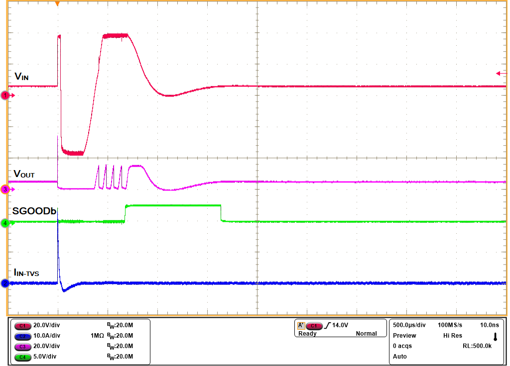
 Figure 5-13 IEC61000-4-5 (+1 kV, 42 Ω)
Signal Line Surge Immunity With TVS3301 at Input of CH1
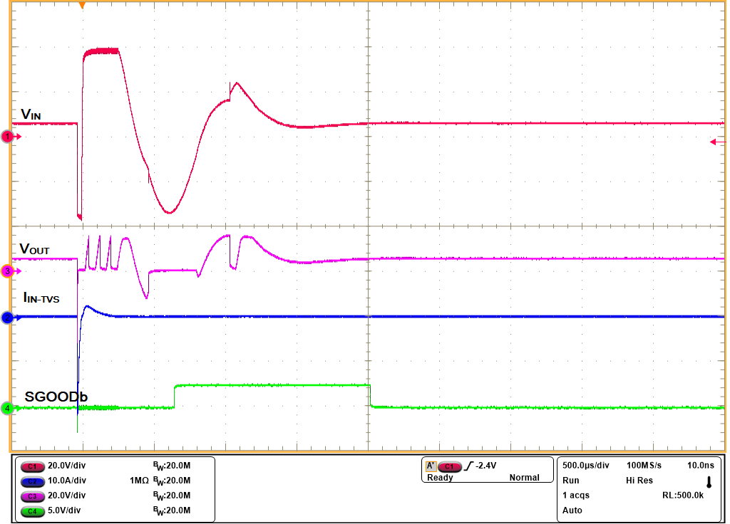
 Figure 5-14 IEC61000-4-5 (–1 kV, 42 Ω)
Signal Line Surge Immunity With TVS3301 at Input of CH1