SLVUC37 March   2021 TPS25814


  1.   Trademarks
  2. 1Introduction
    1. 1.1 Description
    2. 1.2 Features
    3. 1.3 Applications
  3. 2EVM Setup
  4. 3EVM Connectors, Test Points, and Devices
    1. 3.1 Power: 5 V and 3.3 V Supply
    2. 3.2 Power: 1.8 V Supply
    3. 3.3 Power: Barrel Jack Power Connector
    4. 3.4 Switches: ADCIN1 and ADCIN2
    5. 3.5 Switches: CTL, CHG_HI, EN
    6. 3.6 USB Type-C Connector: DFP and UFP
    7. 3.7 Device: TPS25814
    8. 3.8 Device: HD3SS3220
    9. 3.9 Device: TUSB542
  5. 4Testing Procedures
  6. 5PCB Layouts
  7. 6Schematics
  8. 7Bill of Materials

USB Type-C Connector: DFP and UFP

The DFP and UFP USB Type-C® connectors share a similar design. Both use a TVS2200 to help protect against transient voltage events, ESD diodes, and capacitors to bias the SS signals. From a evaluation perspective, the DFP port should be used to evaluate the TPS25814 as a port controller, and the UFP port should be used when evaluating the data capabilities of the EVM.
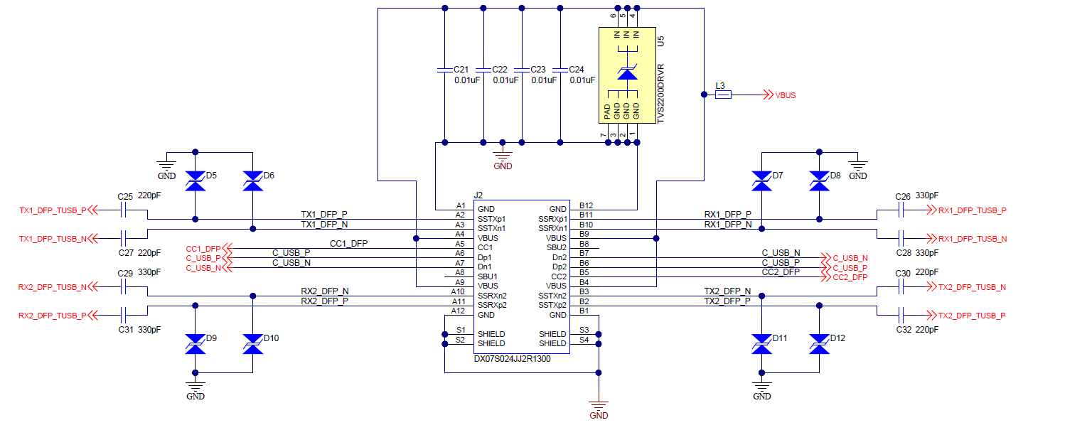
GUID-20210318-CA0I-PDZW-JCJX-LMMKJDDGT5TD-low.png Figure 3-6 USB Type-C Connector