SLVUC37 March 2021 TPS25814
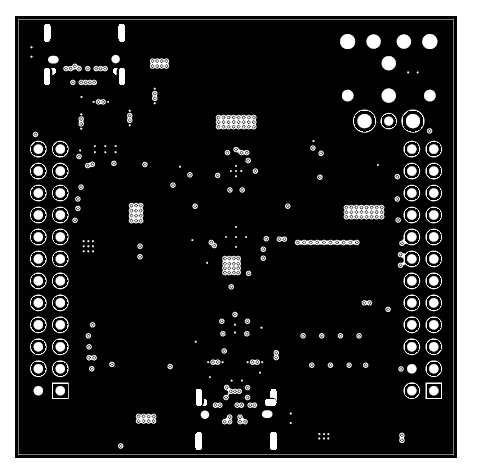
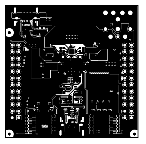
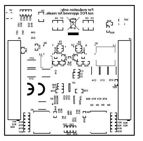
5 PCB Layouts
 Figure 5-1 Top Overlay
 Figure 5-3 Top Layer
 Figure 5-5 High Speed Layer
 Figure 5-7 Power 1 Layer
 Figure 5-9 GND 3 Layer
 Figure 5-11 Bottom Solder
 Figure 5-2 Top Solder
 Figure 5-4 GND 1 Layer
 Figure 5-6 GND 2 Layer
 Figure 5-8 Power 2 Layer
 Figure 5-10 Bottom Layer
 Figure 5-12 Bottom Overlay