SLVUC46D March 2021 – November 2023
4.3.2 Driver Control Page (SPI Device Variant)
 Figure 4-5 Driver Control Page
Starting from left to right in Figure 4-5:
- WAKE: The wake widget controls the nSleep device which directly controls the nSleep pin. The user cannot switch between modes when the device is asleep in SPI mode, and the default for the SPI variant is awake.
- ENABLE DRIVER: Directly controls the DRVOFF pin. When the bridge control is active, the user cannot change between modes or observe the passive diagnostics.
- MODE: Programs the S_MODE
register and alters the appearance of the BRIDGE CONTROL depending on
your selection. There is a difference in MODE options between the DRV824x
and DRV814x device families. The DRV814x devices only operate in one fixed mode
where the user can only switch between high side and low side load connections.
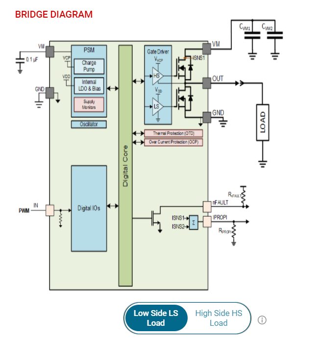
The high side connection connects the load between VM and OUT while the low side
connection connects the load between OUT and GND as can be seen in Figure 4-6.
 Figure 4-6 DRV814x High Side and
Low Side Connections
Figure 4-6 DRV814x High Side and
Low Side ConnectionsIn the DRV824x devices, Phase/Enable mode only has one duty cycle slider while the Independent Half-bridge mode and PWM mode each have two sliders.
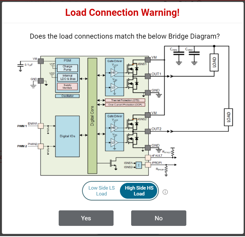
When changing between modes, there is a Load Connection Warning popup. If the load is incorrectly connected and the user attempts to run the motor on the GUI, then the load can damage the device and cause harm to the user. This is especially important when in Independent Half-Bridge mode. The load connection warning appears every time the user selects a new mode or repeatedly selects the current mode. Figure 4-7 shows the pop-up window for the Independent Half-Brige mode selection.
Note: With the DRV824x devices, the GUI allows to switch between high side and low side load connection only using the Independent Half-Bridge mode selection pop-up window. Figure 4-7 DRV824x Independent
Half-Bridge Mode High Side and Low Side Load ConnectionNote: DRV824x-Q1EVMs with HVSSOP package driver device has OUT1 and OUT2 silk screen labels interchanged.
 - BRIDGE CONTROL The Start
Drive button allows the software state machine to start running on the MCU.
Prior to starting, the user can tweak the desired direction, ramp rate, slew
rate, and check for properly connected load connections. After pressing
 ,
the duty cycle sliders become available for modification. The output
automatically soft-starts using the Ramp Rate parameter.
 - PASSIVE/ACTIVE DIAGNOSTICS
The SPI variant features both passive and active diagnostics. The passive
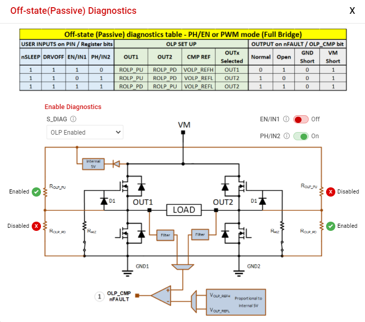
diagnostics also known as Off-line Passive (OLP), can only be used when
ENABLE DRIVER is disabled (Off-state). OLP shows up in a separate
pop-up window as can be seen in Figure 4-8. A representative table from the device data sheet is displayed in this
window for guidance to perform the passive diagnostics. Each row of the table
covers a specific combination of user input selection, the corresponding OLP
setup and load status inference from the OLP_CMP comparator output on the nFAULT
pin. See the device data sheet for more details. The required S_DIAG selection
can be made using the GUI for SPI devices. The required DIAG jumper setting must
be done when WAKE is Asleep for HW devices prior to enabling passive
diagnostics. The nSLEEP and DRVOFF inputs are logic 1 while observing passive
diagnostics. Inputs for EN/IN1 and PH/IN2 are selected using the switches in the
GUI. The pull up can take a few seconds, pull down resistors, and the OLP_CMP
output status to update due to the latency between the EVM hardware and the GUI
application.The Active Open Load Diagnostics are only for High-Side loads with the DRV824x device, Independent Half-Bridge mode, and the DRV814x Half-Bridge device. The Active Diagnostics not exist in the Hardware variants.
 Figure 4-8 Passive Diagnostics
Pop-Up Window
 - FAULTS Press the clear button to clear all the latched faults. Next to the clear button is the CONFIG button for SPI variants. This button allows the user to have more control over the modification of fault reporting. For example, selecting Automatic Retry allows the faults to clear without any manual interference.
- BRIDGE CURRENT The Bridge Current displays moving average and cycle peak load current values calculated from a window of samples of the voltage VIPROPI (VIPROPI = RIPROPI × IPROPI) on the IPROPI output. Each periodic window of samples is referred to as a cycle. The samples are captured using the integrated 10-bit analog to digital converter in the MCU of the EVM. The displayed values are only indicative of the load current during the sampling window. The IPROPI analog output pin available on the header J4 of the EVM can be used for accurate real-time measurement using a multimeter or for capturing the load current waveform using an oscilloscope. Current scaling is done by selecting a desired RIPROPI resistor with the IPROPI jumper setting on the current limit header J2 of EVM. See Section 2.2.5. Match the RIPROPI setting on the GUI with the IPROPI jumper setting of the EVM.
Every control also has a help tip associated to quickly help the user while running the GUI.