SLVUC46D March   2021  – November 2023


  1.   1
  2.   Abstract
  3.   Trademarks
  4. 1Introduction
    1. 1.1 Overview
      1. 1.1.1 Purpose and Scope
  5. 2Evaluation Hardware Overview
    1. 2.1 Connections Overview
    2. 2.2 Connection Details
      1. 2.2.1 Common Connectors and Headers Across all EVM Variants
      2. 2.2.2 MCU Reset and User Button
      3. 2.2.3 Communication Interfaces
      4. 2.2.4 Supply Input
      5. 2.2.5 Current Limit Header (RIPROPI)
      6. 2.2.6 Device Signal and Control Header
      7. 2.2.7 Device Signal Test Points
    3. 2.3 LED Indicators
    4. 2.4 Headers and Connectors (Hardware Device Variant)
    5. 2.5 Headers and Connectors (SPI variant)
  6. 3EVM GUI Control Application
    1. 3.1 MSP430 FET Drivers
    2. 3.2 Cloud-based GUI
    3. 3.3 Local Installation
  7. 4EVM GUI Operation
    1. 4.1 Hardware Setup
    2. 4.2 Launching the DRV824x_DRV814x-Q1EVM GUI Application
    3. 4.3 Using the DRV824x_DRV814x-Q1EVM GUI Application
      1. 4.3.1 Register Map Page (SPI Device Variant)
      2. 4.3.2 Driver Control Page (SPI Device Variant)
      3. 4.3.3 Driver Control Page (HW Device Variant)
      4. 4.3.4 Updating Firmware
  8. 5Revision History

Communication Interfaces

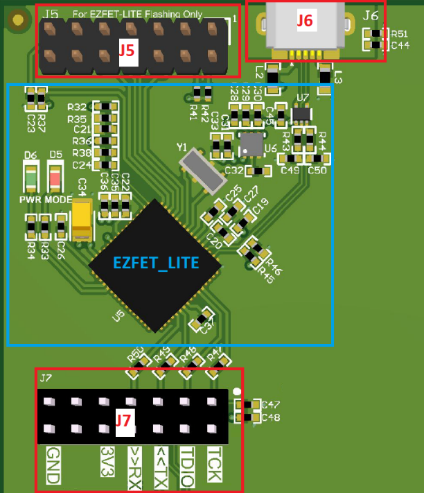
The micro-USB connection is the primary communication interface from your PC to the EVM GUI Application. Figure 2-3 illustrates connection associated with communications between the EVM and GUI, as well as firmware programming (some components have been removed from the picture for clarity).

The EZFET_LITE (based on the Texas Instruments MSP430F5528) is programmed at the factory with firmware that implements UART and JTAG over USB.

GUID-20210421-CA0I-4GSK-N9BQ-CCFKXF7QQTC2-low.png

Figure 2-3 EVM Communication Connections

Table 2-2 describes each communication connection.

Table 2-2 Communication Description
Designator Description
J5 MSP430 14-pin JTAG interface. Used for programming EZFET_LITE firmware on MSP430F5528 during manufacturing and not used during normal user operation.
J6 Micro-USB interface for main MCU (MSP430G2553). Both UART and JTAG are routed over this connection.
J7 These headers route communications and 3.3 V to the main MCU. Jumpers must be installed on 3V3, RX, TX, TDIO and TCK positions.