SLVUC46D March 2021 – November 2023
2.2 Connection Details
See Table 2-1 for a brief comparison of both the DRV824x-Q1EVM and DRV814x-Q1EVM in the VQFN HotRod™ package. The 28-pin leaded package (HVSSOP or HTSSOP) version of EVM leverages much of the same design and is also covered by this document. From a firmware and GUI perspective, the two package options are interchangeable. The 40x40mm lower-right quadrant of the EVM is modified to the H-bridge and half-bridge devices. The DRV814x-Q1 VQFN device orientation is rotated for better power and thermal characteristics, taking advantage of the busbar-like footprint of the HotRod™ package.
A supply voltage ranging from +4.5 VDC to +36 VDC from a battery or a DC voltage source is connected to the voltage supply pins. This connection includes fuse, reverse polarity, and transient protection.
The OUT1 and OUT2 banana jacks on the DRV824x-Q1EVM can be connected to a brushed motor, inductor, or latched relay coil when used in PWM or phase/enable (PH/EN) mode. When used in independent half-bridge mode, the OUT1 pin can drive one load and the OUT2 pin can drive a second load.
| DRV814x-Q1EVM | DRV824x-Q1EVM |
|---|---|
|
|
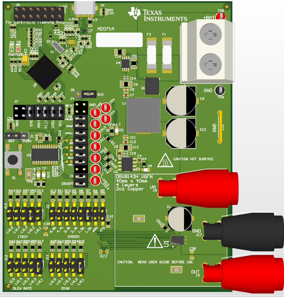 | 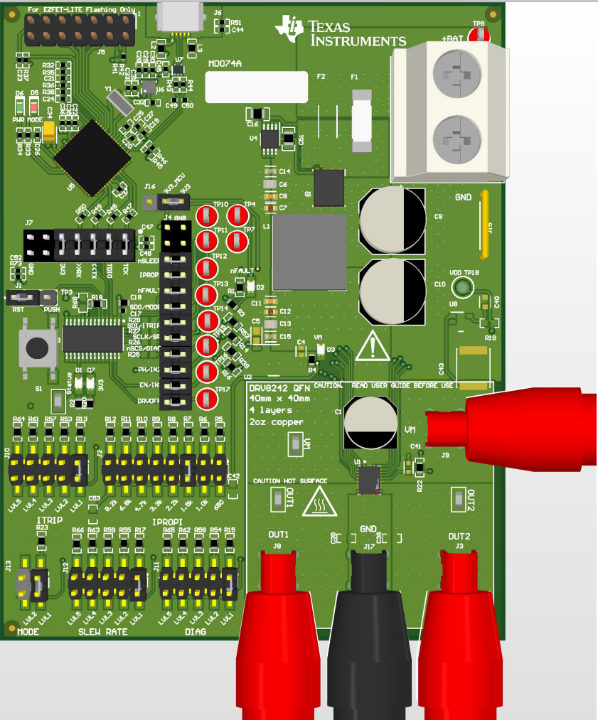 |